Revision 1.03
4-8 ChannelMaster TX7 Transmitter
CMTX7 Front Panel
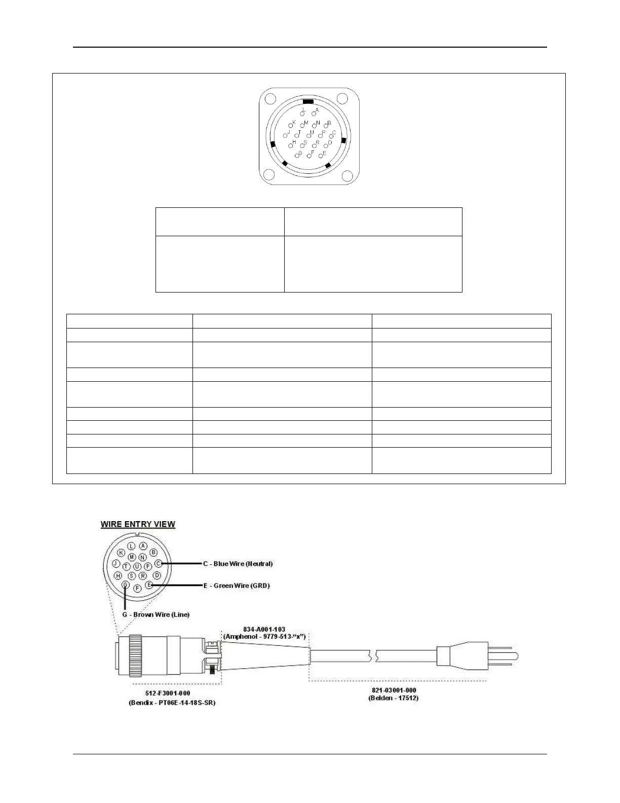
Power Connector
Mating Connector
Nucomm P/N:
512-M2001-000
Detoronics P/N:
DT02H-14-18PN
Nucomm P/N:
512-F3001-000
Mil-C-26482, Series 1
P/N: MS3116F-14-1PS
PIN DESCRIPTION NOTES
C AC Neutral
E Chassis GND Connected to Chassis and Pins H
and S internally.
G AC Line
H, S GND (DC GND RETURN) Connected to Internal DC ground,
Pin E, and Chassis internally.
P, U, B +DC IN DC power
M RS232 TX / OUT For Remote Control
L RS232 RX / IN For Remote Control
SHELL Chassis GND (Can be used to shield power ca-
bles.)
Figure 4-8: Power and RS-232 Connector Pin-Outs and Part Information
Figure 4-9: AC Line Cord Construction