Revision 1.03
Operation 5-1
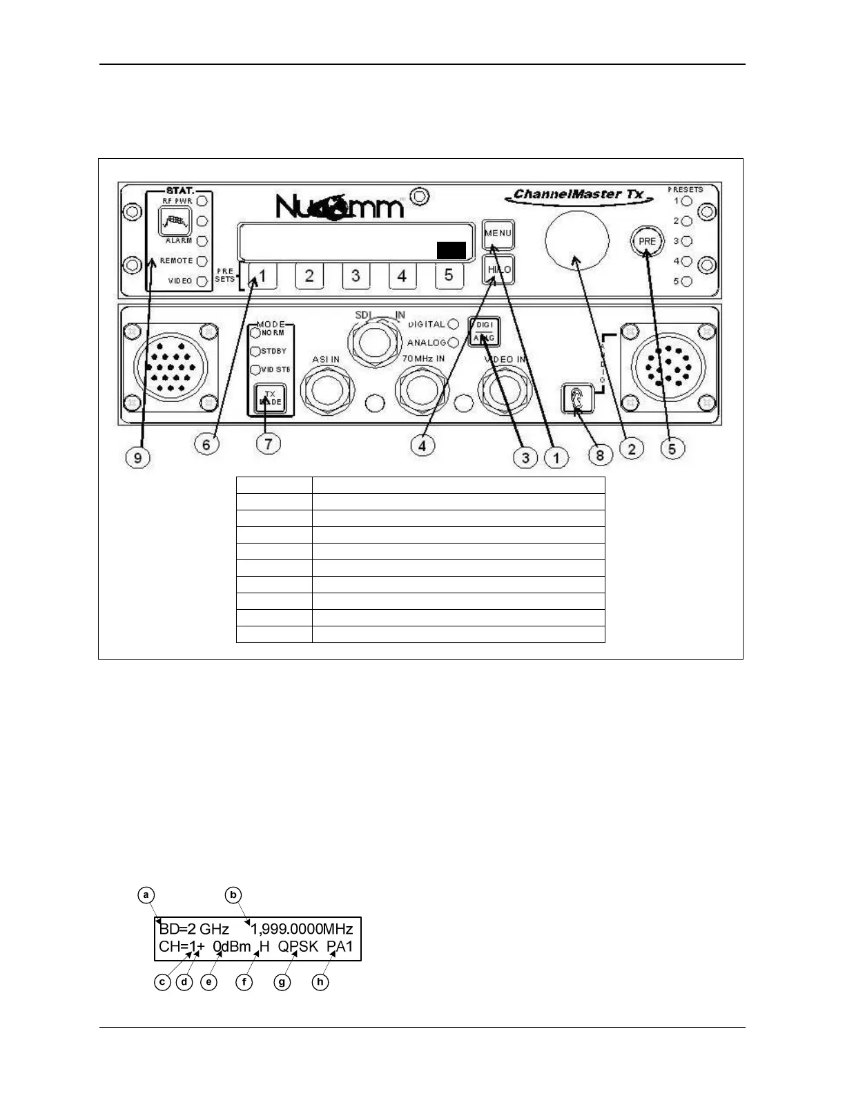
5. OPERATION
ITEM DESCRIPTION
1 Menu Button
2 “Quick Knob” and Selection Pushbutton
3 Digital/Analog Mode Select Button
4 HI/LO Button
5 PRE Button
6 1 - 5 Selection Buttons
7 TX (Transmit) Mode Button
8 Audio Quick Key Button (non-XLR Model only)
9 Status Display
Figure 5-1: ChannelMaster TX7 Front Panel Controls and Indicators
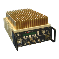
5.1 Power Up Displays
Upon powering up the unit, you will see
three quick screens showing the equip-
ment type, the model number, and the
serial number. After that, the unit will
display the DEFAULT screen, which will
look similar to the following (depending
on your configuration).
The DEFAULT screen displays:
(a) The current Frequency Band
(b) The current Channel Frequency
(c) The current Channel
(d) The current channel Offset
(e) The RF Output Level in dBm
(f) The current Power Level (HI / LO)
(g) The current Modulation Type
(h) The current Preset selected (if any)
Once this screen appears, options and
settings can then be changed and initial-
ized through the use of the front panel
"Quick-Keys" and pre-set buttons, via
the menu system, or by making selec-
BD=2 GHz 1,999.000MHz
CH=1+ 0dBm H QPSK PA1