Revision 1.03
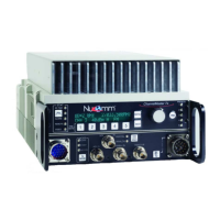
5-10 ChannelMaster TX7 Transmitter
tipath environments (around
buildings, across water, etc) by
increasing the time delay be-
tween data segments. Increasing
the GI (1/4 is the maximum set-
ting) increases link robustness
but reduces the overall data rate,
as less time is made available for
payload transmission. Con-
versely, moving the GI towards
1/32 (the minimum) decreases
link robustness but allocates
more bits to payload.
(b) The CR controls how much
error correction overhead is in-
cluded in the data stream. To
compensate for a poor link, mov-
ing the CR towards 1/2 (maxi-
mum error correction)
increases link robustness as bits
are re-allocated from payload to
error correction. Moving the CR
towards 7/8 (minimum error cor-
rection) allocates bits from error
correction to payload.
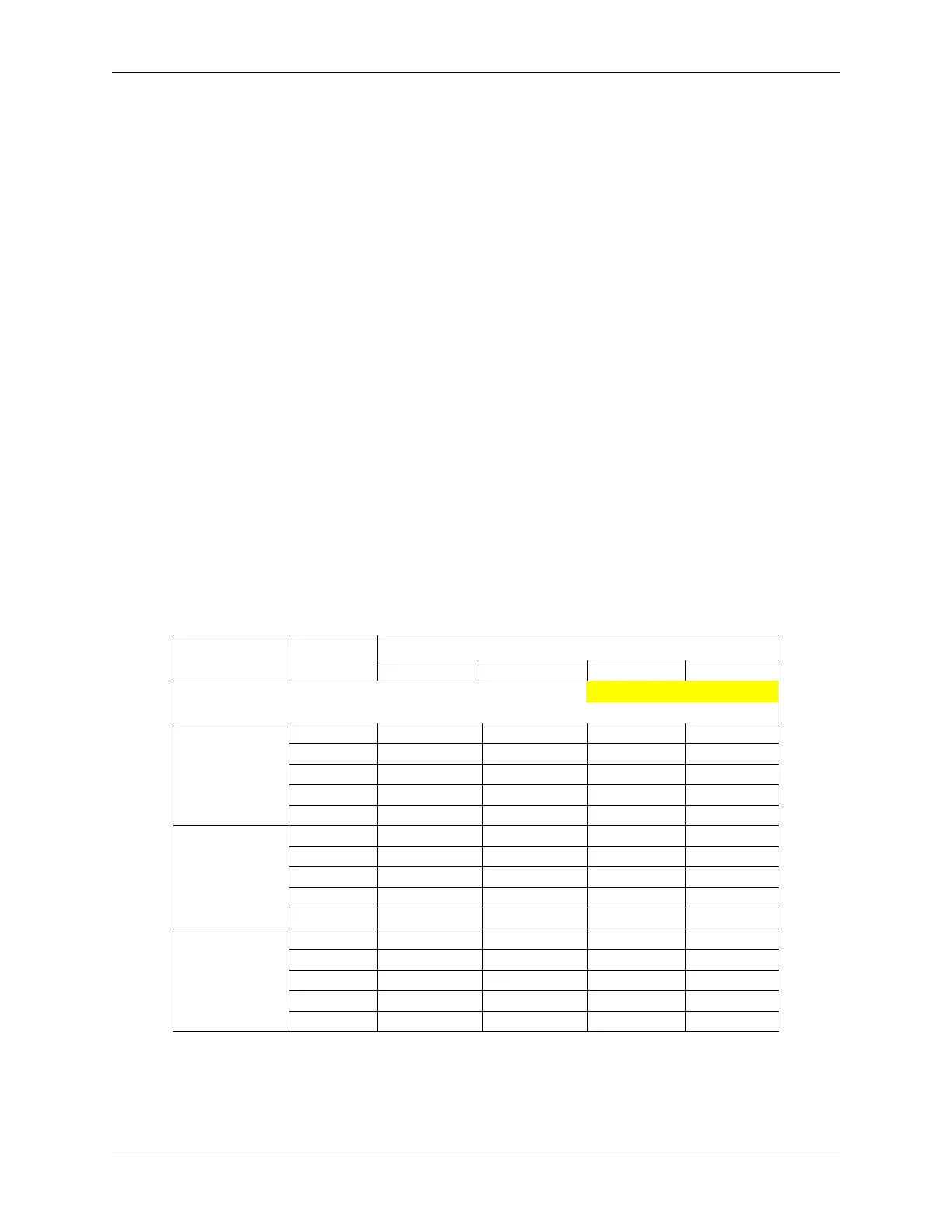
COFDM Data Rate
Tables 5-1 through 5-3 show the data
rates which can be achieved by modify-
ing the COFDM parameters.
Note: When inputting ASI signals, the
data rate should be set to approximately
1-2 kbps above the ASI input rate.
Table 5-1: ChannelMaster 8 MHz B/W Data Rates
Guard Interval
Modulation
System
Code
Rate
1/32 1/16 1/8 1/4
IF = 9.142857 MHz Flo = 60.857143 MHz
BW = 8 MHz
Clk=36.571429 Mbit/s
Data Rate (Mbit/s)
1/2 6.032086 5.854671 5.529412 4.976471
2/3 8.042781 7.806228 7.372549 6.635294
QPSK
3/4 9.048128 8.782007 8.294118 7.464706
5/6 10.053476 9.757785 9.215686 8.294118
7/8 10.55615 10.245675 9.676471 8.708824
1/2 12.064172 11.709342 11.058824 9.952942
2/3 16.085562 15.612456 14.745098 13.270588
16-QAM
3/4 18.096256 17.564014 16.588236 14.929412
5/6 20.106952 19.51557 18.431372 16.588236
7/8 21.1123 20.49135 19.352942 17.417648
1/2 18.096258 17.564013 16.588236 14.929413
2/3 24.128343 23.418684 22.117647 19.905882
64-QAM
3/4 27.144384 26.346021 24.882354 22.394118
5/6 30.160428 29.273355 27.647058 24.882354
7/8 31.66845 30.737025 29.029413 26.126472