NVIDIA Jetson TX2/TX2i OEM Product Design Guide
JETSON TX2/TX2i OEM PRODUCT | DESIGN GUIDE | 20180618 43
Trace Impedance Diff pair
- 100Ω is the spec. target. 95/85Ω are
implementation options (Zdiff does not
account f or trace coupling)
- 95Ω should be used to support DP-HDMI co-
lay out as HDMI 2.0 requires 100Ω impedance
(see HDMI section for addition of series
resistor R
S
).
- 85Ω can be used if eDP/DP only & is
preferable as it can provide better trace loss
characteristic performance. See Note 1.
Trace Length, Spacing & Skew
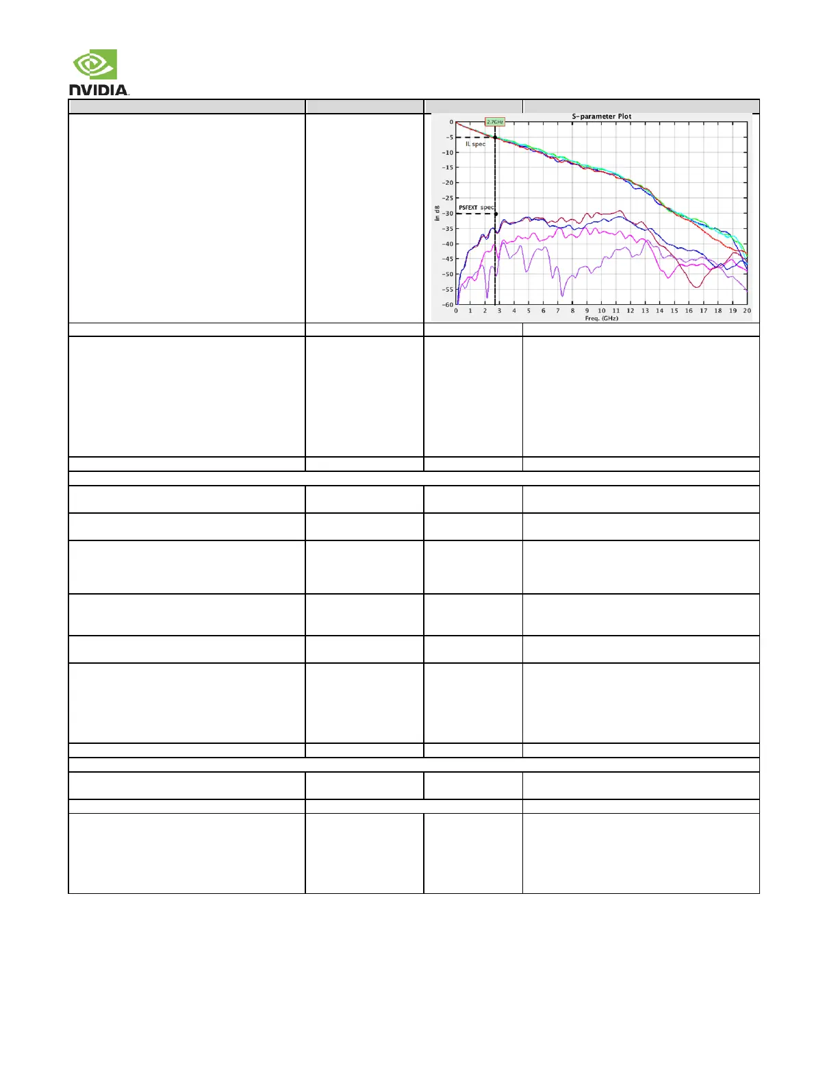
Trace loss characteristic @ 2.7GHz
The following max length is derived based on this
characteristic. See note 2.
Max PCB Via dist. from module conn. RBR/HBR
HBR2
No requirement
7.63 (0.3)
Max trace length from module to connector
RBR/HBR (Stripline / Microstrip)
HBR2 (Stripline)
HBR2 (Microstrip, 5x / 7x)
165 (1137.5)/(975)
101.6 (700)
89 (525) / 101.6 (600)
175ps/inch assumption for Stripline, 150ps/inch
for Microstrip.
Trace spacing (Pair-Pair) Stripline
Microstrip (HBR/RBR)
Microstrip (HBR2)
Trace spacing Stripline/Microstrip
(Main Link to AUX)
Max Intra-pair (within pair) Skew
- Do not perform length matching within
breakout region
- Do trace length matching before hitting
discontinuity (i.e. matching to <1ps
before the vias or any discontinuity to
minimize common mode conversion).
Max Inter-pair (pair-pair) Skew
Max GND transition Via distance
For signals switching reference layers, add
symmetrical GND stitching Via near signal Vias.
Impedance dip
Recommended via dimension Drill/Pad
for impedance control Antipad
Via pitch
97
92
200/400
>840
@ 200ps
@ 35ps
um
um
um
The via dimension must be required for the HDMI-
DP co-layout condition.