UG8000-00 November 2002
Page 1-29
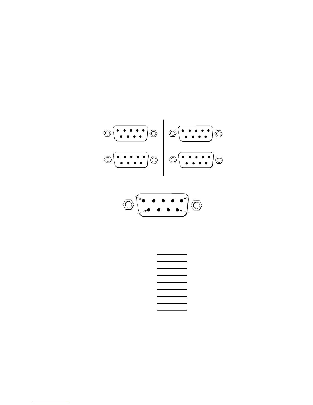
CONTROL CONNECTORS (ALL MODELS)
Connect RS-422 serial data cables from your control system to the router CTRL1 9-pin
D connectors. One cable is required for the Primary Control module (PRIMARY
CTRL1) and another cable for the Secondary Control module (SECONDARY CTRL1).
If you use more than one control system, connect the alternate control system to the
CTRL2 connectors.
Figure 1-11 provides the RS-422 control cable connector pin-outs.
Figure 1-11. Control Cable Connector Pin-Outs
CTRL 1
CTRL 2
DIAG
PRIMARY SECONDARY
CTRL 1
CTRL 2
DIAG
MT6000-00
1 - Ground
2 - Transmit A-
3 - Receive B+
4 - Receive Common
5 - N/C
6 - Transmit Common
7 - Transmit B+
8 - Receive A-
9 - Ground
Ground - 1
Receive A- - 2
Transmit B+ - 3
Transmit Common - 4
N/C - 5
Receive Common - 6
Receive B+ - 7
Transmit A- - 8
Ground - 9
CONTROL CABLE 9-Pin FEMALE ROUTER CABLE 9-Pin MALE
Signal Pin # Pin # Signal
Pin 1
Pin 9
Pin 5
Pin 6
Wiring Side
 Loading...