UG8000-00 November 2002
Page 1-33
POWER SUPPLY ALARMS CONNECTOR (6064/6128)
Alarms to indicate a power supply failure are provided for both the main and redundant
power supplies. The PS ALARMS connector includes normally closed connections
from pin 1 to COM and pin 2 to COM, corresponding to Power Supply 1 (main) and
Power Supply 2 (redundant), respectively.
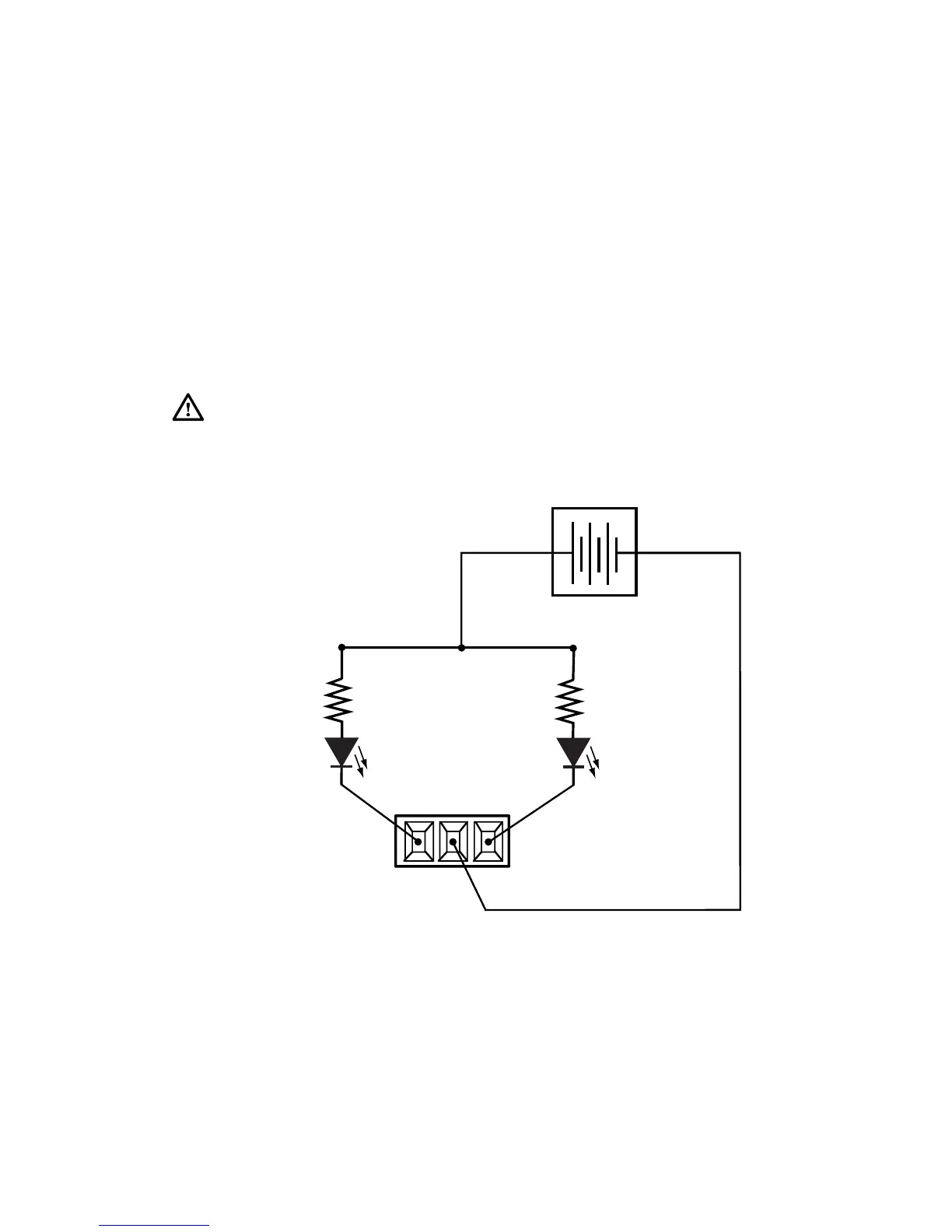
To indicate an alarm, connect a DC power source and a light to the contacts as shown
in Figure 1-15. The light will remain on whenever the power supply is in operation and
will turn off if the power supply fails or is removed. As an alternative, a circuit using
lights that are normally off and that turn on to indicate a failure may also be constructed
using relays as shown previously for the system alarms connector.
Figure 1-15. Power Supply Alarms Connector (6064/6128)
Caution: The power supply for the alarm circuit must not exceed 30 VDC or 150 mA.
Load resistor value depends on power supply voltage.
1
C
O
M
2
PSALARMS
1AND2
NORMALLY
CLOSED
5VDCPowerSupply(typical)
+-
400ohms
(typical)
400ohms
(typical)
 Loading...