UG8000-00 November 2002
Page 1-32
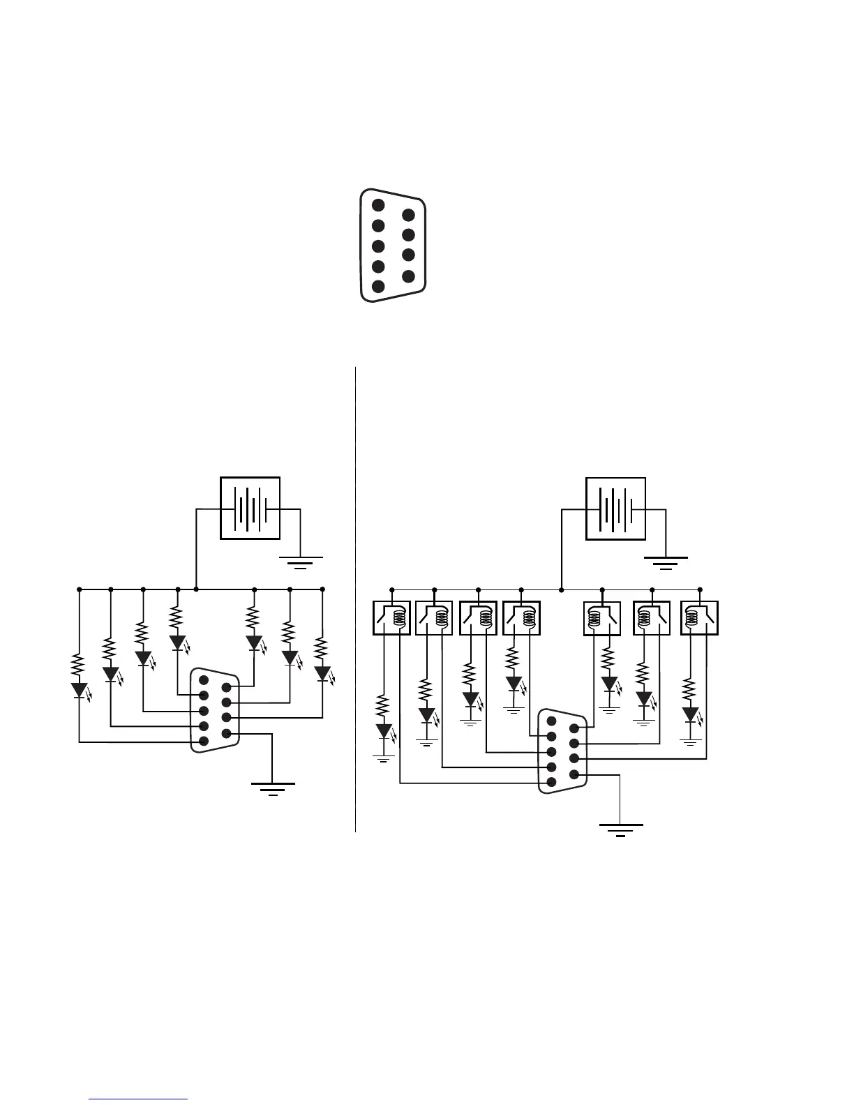
Figure 1-14. Typical Alarm Connections
Alarm_COM-1
Alarm_1-2
Alarm_2-3
Alarm_3-4
Alarm_4-5
6-Alarm_5
7-Alarm_6
8-Alarm_7
9-Alarm_COM
ALARMS9-PinD
FemaleConnector
Pin Pin
C
O
M
DCPowerSource
+-
C
O
M
Userelay
normallyclosedcontact
+-
NormallyONLEDsturnOFF
toindicatefailure.
TYPICALCIRCUIT1
NormallyOFFLEDsturnON
toindicatefailure.
TYPICALCIRCUIT2
DCPowerSource
Internalconnectionofalarm
pinstoCOMisclosedwhen
alarmisoff,openwhenalarm
ison.
Internalconnectionofalarm
pinstoCOMisclosedwhen
alarmisoff,openwhenalarm
ison.
Wiring Side
 Loading...