UG8000-00 November 2002
Page 2-15
Replacing a Primary Crosspoint
If it becomes necessary to remove a crosspoint for service, simply depress the
‘Replace XPT’ button (on the center, redundant crosspoint module) for the appropriate
output bank (LH = 1–128, RH = 129–256). The yellow, ‘active’, LED on the selected
primary will go out. This will automatically make the redundant crosspoint active
(illuminating its yellow, ‘active’, LED and setting the Replace XPT button to full
brightness), allowing the primary crosspoint to be removed from the system.
When the standby crosspoint is activated, a switchover is initiated during the video
vertical interval period. This ensures that none of the signal paths will be interrupted.
To reinstall a primary crosspoint, simply plug it into the appropriate slot, ensure that
only the green ‘power’ indicator is lit and press the ‘Standby Mode’ button on the
redundant module. This will return the primary card to normal operation and the status
LEDs will show it as active.
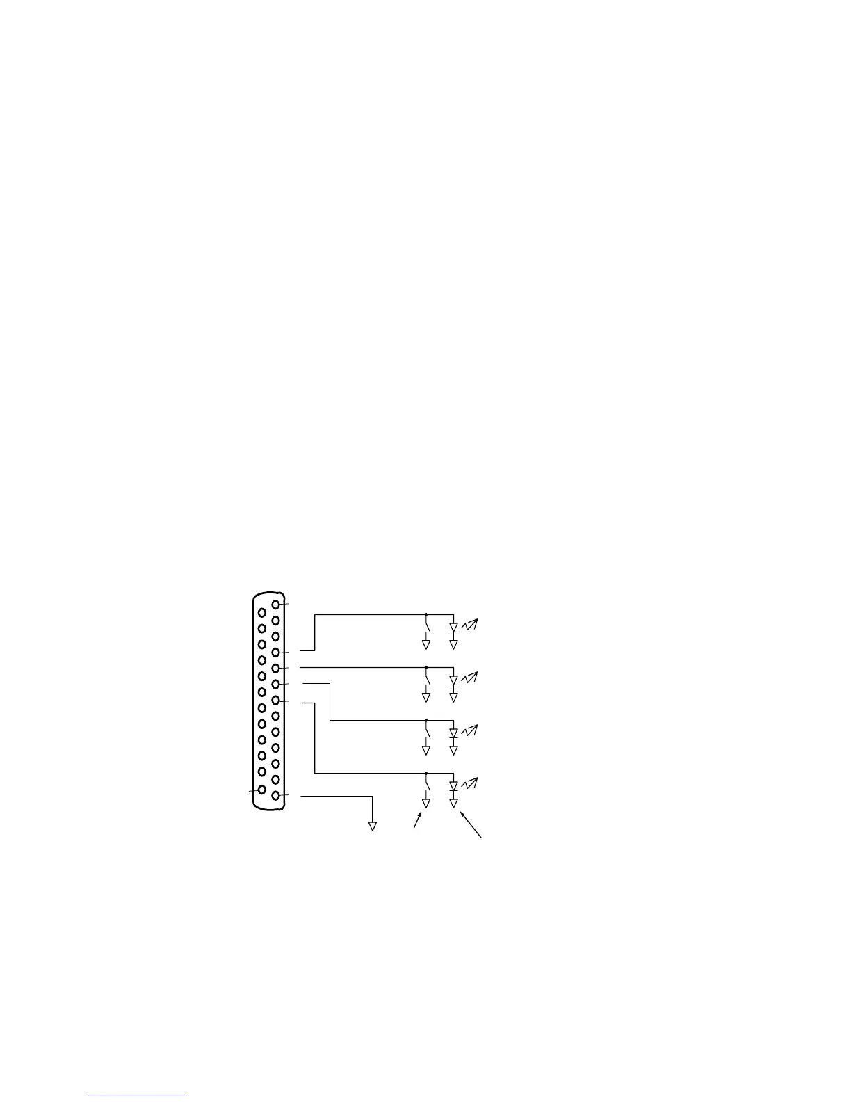
Remote Control Connections
An external circuit can be constructed for remote control of the redundant crosspoint
function. The circuit should be constructed using momentary switches that have a
series resistance of less than 50 ohms and are connected in parallel with an LED that
has its cathode attached to GND. The output signal from the frame is nominally +3.3
volts. The diode selected for this use should have an If max (maximum forward bias
current) of 10mA, and Vf (forward bias voltage) of 1.5–2.2 volts.
Figure 2-3. Remote control connector pinout and required circuit
To activate external control, press the “Remote Control Enable” button—its brightness
level indicates current status, i.e. half brightness indicates local control (or, remote
control off) and full brightness indicates remote and local control.
Left Crosspoint
(Outputs 1 to 128)
 Loading...