UG8000-00 November 2002
Page 1-34
POWER SUPPLY ALARMS CONNECTOR (6256/8256)
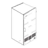
The NV6256 and NV8256 routers use the 6257 external power supply frame,
containing up to 8 main and redundant power supply modules. Alarms to indicate a
power supply module failure are provided for each of the main and redundant power
supplies contained in the 6257 Power Supply frame.
The PS ALARMS connector on the back of the 6257 power supply frame provides
normally closed connections from the active pin for each power supply alarm to its
associated COM (common) pin. To indicate an alarm, connect an external LED
indicator as shown in Figure 1-16. The figure shows the pin-out of the connector and
typical connections. Alarms 1-8 indicated on the pin-out drawing correspond with
power supplies 1-8 in the 6257 frame.
Caution: The power supply for the alarm circuit must not exceed 30 VDC or 150 mA.
Load resistor value depends on power supply voltage.
 Loading...