UG8000-00 November 2002
Page 1-35
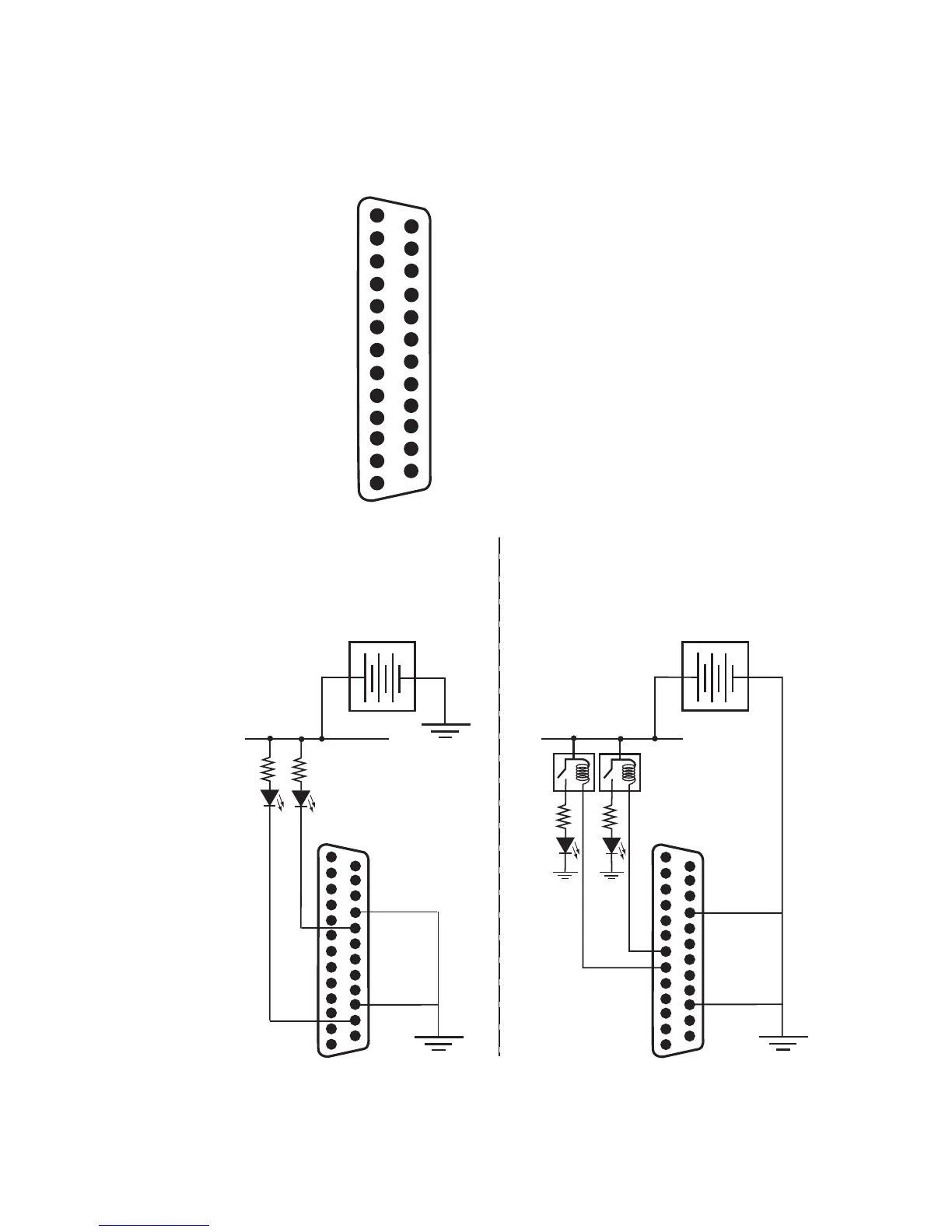
Figure 1-16. Power Supply Alarms Connector (6256/8256)
PS8_Opto_COM-1
PS7_Opto_COM-2
PS6_Opto_COM-3
PS5_Opto_COM-4
PS4_Opto_COM-5
14-GND
15-GND
15-GND
17-PS2_Opto_COM
6257PSALARMS25-PinD
FemaleConnector,WiringSide
Pin Pin
DCPowerSource
+-
Userelaynormally
closedcontact
NormallyONLEDsturnOFF
toindicatefailure.
TYPICALCIRCUIT1
NormallyOFFLEDsturnON
toindicatefailure.
TYPICALCIRCUIT2
Internalconnectionofalarm
pinstoCOMisclosedwhen
alarmisoff,openwhenalarm
ison.
PS3_Opto_COM-6
PS8_Opto_C-7
PS7_Opto_C-8
PS6_Opto_C-9
PS5_Opto_C-10
PS4_Opto_C-11
PS3_Opto_C-12
GND-13
18-PS2_Opto_C
19-GND
20-GND
21-GND
22-GND
23-PS1_Opto_COM
24-PS1_Opto_C
25-NC
DCPowerSource
+-
PS2_Com
PS1_Com
PS2
PS1
PS2
PS1
PS2_Com
PS1_Com
Connectionexamplesareshown
belowforpowersupplies1and2.
Connectionsmaybemadeforall
8powersuppliesinthe6257frame.
Maxload:
30VDC/150mA
Maxload:
30VDC/150mA
 Loading...