HeatWater.com | WaterService@nyle.com | (800) 777-6953 IM-e360-122023 IM-e360-122023 HeatWater.com | WaterService@nyle.com | (800) 777-6953
35
Startup Procedure and Checklist (Continued)
F For Ducted Systems: Ensure any dampers
in the duct system are open, and if ducting is
shared between multiple heat pumps, then all
heat pumps on the duct system should be run
and measured together. Initiate “Max Fan” on
the control interface, in the “Diagnose” section
(service jumper required on terminals 24V and
i7). Using a manometer or magnahelic gauge,
take a negative pressure reading in the intake
duct near the evaporator, and a positive pres-
sure reading in the discharge duct near the fan
housing. Seal access holes when done. The
difference between the two readings should not
exceed 1.5" w.c.g.
Measured Discharge
______________ In. w.c.g.
Measured Intake
______________ In. w.c.g.
F Power down the heat pump. Locate the defrost
heater contactor in the electrical enclosure.
Measure the resistance between the terminals
listed in Table 12 and ensure resistance is within
+5% or -10% of the listed value. If not, it will be
necessary to locate any bad elements.
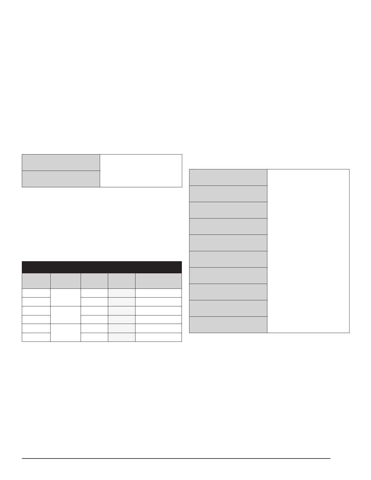
Table 12: Defrost Element Resistance Values
Ohms Between Contactor Terminals
Heat
Pump
Terminals Target Actual
Ohms
Single Element
230V
T1-T2
5.9 44
460V 25.6 64
230V
T2-T3
5.9 44
460V 25.6 64
230V
T1-T3
5.9 44
460V 25.6 64
Note: At this point if all Pre-Startup and Startup procedures
and checks have been completed, it is safe to turn the heat
pump “ON” via the control interface, which will enable nor-
mal compressor operation.
F Double check that all conguration options on
the control interface are set as required for this
project.
F Typically, a demand for heating should start, as
the tanks should be cold. If not, dump hot water
until a demand is initiated. If BMS control is in-
volved, ensure that BMS has not “disabled” the
heat pump.
F Wait a total of 20 minutes before taking the fol-
lowing operational readings after a heat demand
initiates. This includes several minutes of startup
delay before compressor operation begins, and
several more minutes of continuous operation.
Pressures and readings should be somewhat
stable before readings are taken.
F Record the following readings from the control
interface:
Condenser Flow Rate
______________ GPM
Ambient Temperature
______________ Deg. F.
Condenser EWT
______________ Deg. F.
Condenser LWT
______________ Deg. F.
Superheat
______________ Deg. F.
Discharge Temperature
______________ Deg. F.
Liquid Line Temperature
______________ Deg. F.
Suction Temperature
______________ Deg. F.
Suction Line Pressure
______________ psi
Discharge Line Pressure
______________ psi