BA_OCHSNER AIR EAGLE_414_717_V06_EN.docx Page 72 of 76
14 List of figures
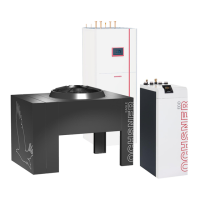
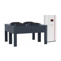
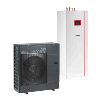
Figure 1: System overview............................................ 6
Figure 2: EAGLE outdoor unit ....................................... 7
Figure 3: Outdoor unit minimum clearances (in mm) .... 8
Figure 4: Outdoor unit dimensions (in mm) ................... 8
Figure 5: Outdoor unit main components .................... 10
Figure 6: Outdoor unit conduits ................................... 10
Figure 7: EAGLE outdoor unit (view from below), fixing
holes in the outdoor unit legs (dimensions in mm) ...... 11
Figure 8: Strip foundation (dimensions in mm) ........... 12
Figure 9: Spot foundation (dimensions in mm) ........... 12
Figure 10: Installation on concrete plinth (dimensions in
mm) ............................................................................ 13
Figure 11: EAGLE outdoor unit secured with structure-
borne noise attenuating fixings ................................... 14
Figure 12: Flat roof installation of EAGLE outdoor unit
(dimensions in mm) .................................................... 14
Figure 13: Indoor unit detailed view ............................ 15
Figure 14: View from above ........................................ 16
Figure 15: Minimum wall clearances ........................... 16
Figure 16: Indoor unit dimensions ............................... 17
Figure 17: Indoor unit tilt height .................................. 17
Figure 18: Indoor unit connection dimensions ........ 17
Figure 19: Indoor unit air vent valve ............................ 18
Figure 20: Draining and filling detailed view................ 18
Figure 21: T200 hydraulic schematic ...................... 19
Figure 22: Main components in T200 indoor unit ........ 20
Figure 23: Minimum clearances (in mm) ................ 21
Figure 24: Dimensions (in mm) ................................... 21
Figure 25: Hydraulic connections and labels, T200
refrigeration 22
Figure 26: Removing the fixing screw..................... 23
Figure 27: Pull the sensor from the buffer tank. ...... 23
Figure 28: Undoing the plug-in connectors ............. 23
Figure 29: Removing the hydraulic hoses .............. 24
Figure 30: Undoing the connecting screws............. 24
Figure 31: Separating the appliance sections 1 ......24
Figure 32: Separating the appliance sections 2 ......24
Figure 33: Setting down the T200 top section ........24
Figure 34: Assembling the appliance sections 1 .....25
Figure 35: Positioning aid .......................................25
Figure 36: Assembling the appliance sections 2 .....25
Figure 37: Drain hose, safety valve ........................26
Figure 38: Filling the heating system ......................27
Figure 39: Draining the buffer tank .........................29
Figure 40: Draining the DHW tank ..........................29
Figure 41: T200 DHW tank sacrificial anode ..........29
Figure 42: Max. height difference ................................31
Figure 43: Oil lift bends ...............................................31
Figure 44: Conduit to house (dimensions in mm) ........31
Figure 45: Power supply .............................................33
Figure 46: PSU signal contact .....................................34
Figure 47: Pipe marking in the heat pump indoor unit .35
Figure 48: Wiring overview ..........................................36
Figure 49: T200 electrical connection .....................38
Figure 50: T200 indoor unit cable entry ......................38
Figure 51: T200 indoor unit connection terminals .......39
Figure 52: Outdoor unit wiring .....................................40
Figure 53: Setting the flow rate ...................................47
Figure 54: Reading the flow rate .................................47
Figure 55: Operation ...................................................48
Figure 56: Operation ...................................................48
Figure 57: Pump curve ................................................59
Figure 58: Performance diagrams EAGLE 717 ...........60
Figure 59: Performance diagrams EAGLE 414 ...........60
15 List of tables
Table 1: Cable selection ............................................. 33
Table 2: Wiring diagram .............................................. 36
Table 3: Nominal flue rates ......................................... 47
Table 4: Troubleshooting ............................................ 50
Table 5: OTE Error Codes .......................................... 52
Table 6: Specification (part 1) ..................................... 56
Table 7: Specification (part 2) .....................................57
Table 8: T200 Specification .........................................58
Table 9: Pressure drop................................................59