EasyManua.ls Logo

Ochsner Air Eagle 717 - Main Components; Choosing the Installation Location

Ochsner Air Eagle 717
76 pages
Print Icon
To Next Page IconTo Next Page
To Previous Page IconTo Previous Page
Loading...
BA_OCHSNER AIR EAGLE_414_717_V06_EN.docx Page 20 of 76
Main components
1
Magnesium anode
2
Air vent valve (MFA)
3
Electric booster heater 8.8 kW (MFA)
4
Safety valve (MFA)
5
3-way switching valve (MFA)
6
Electrical connection
7
Cable entries
8
Maintenance flange
9
Drain stopcock
10
Buffer tank (100 l)
11
Drain stopcock
12
Heating circuit pump
13
Buffer charging pump
14
DHW tank (168 l)
15
Condenser (plate heat exchanger)
16
High limit safety cut-out (MFA)
17
Air vent valve
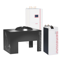
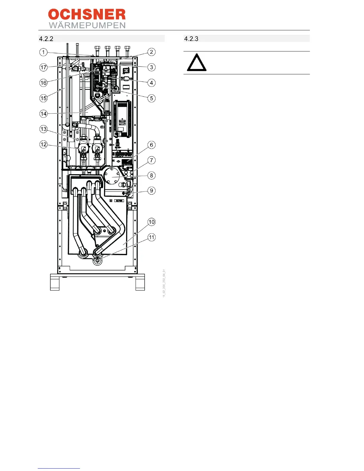
Figure 22: Main components in T200 indoor unit
Choosing the installation location
CAUTION
Do not install the appliance in damp
rooms!
Install the appliance in a frost free and dry room
near the draw-off point. In order to reduce line
losses, keep the distance between the indoor unit
and the outdoor unit small.
Ensure that the floor has adequate load bearing
capacity and is sufficiently level (for weight, see
section 13, Specification). The room must not be
endangered by explosive dust, gases or vapours.
If installing the appliance in a boiler room with
other heating appliances, ensure that their
operation is not affected.

Table of Contents

Related product manuals