OFITE, 11302 Steeplecrest Dr., Houston, TX 77065 USA / Tel: 832-320-7300 / Fax: 713-880-9886 / www.ote.com 44
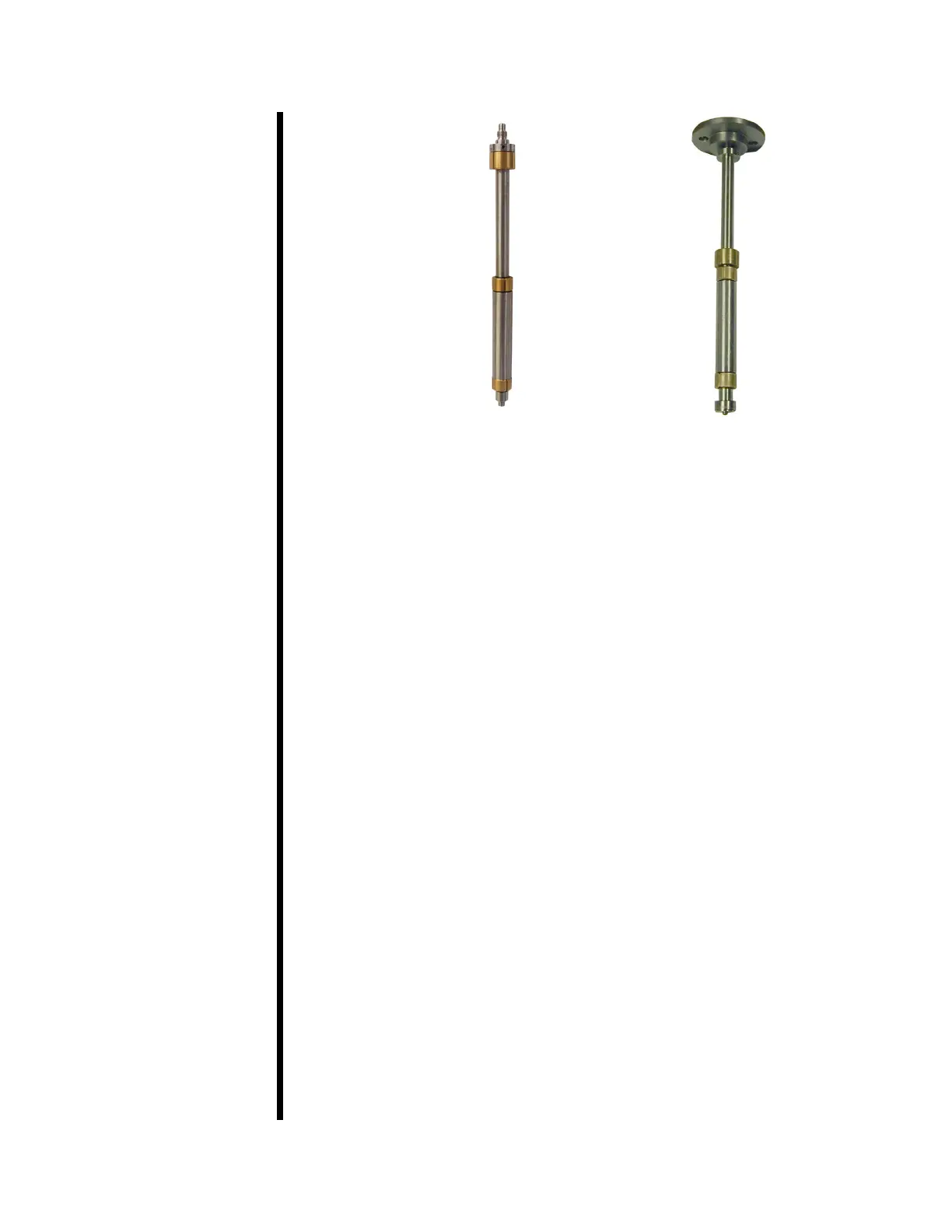
Rotor Assembly
Rotor Assembly with
Slurry Cup Table
7. Thread the slurry cup table onto the rotor shaft assembly.
Pour a small amount of mineral oil into the vessel. This will act as a
cushion when inserting the rotor assembly.
8. Insert the rotor assembly into the drive housing. Press down on the
slurry cup table until it falls into place.
9. Replace the cover and gland underneath the test cell before beginning
another test.
Filters
The instrument has an air lter and an air dryer. Both are located inside
the cabinet on the left-hand side (see photo on page 47). Periodically
check both of these for accumulated water. Unscrew the plug on the
bottom and let the water drain.
The instrument has two oil lters. Both are inside the cabinet. The high-
pressure lter is on the right-hand side and the low-pressure lter is on
the bottom below the cell (see photo on page 47). The low-pressure
lter should be replaced yearly. The high-pressure lter should be cleaned
when the ow of oil back into the reservoir is obstructed (see page
48 for instructions).