OFITE, 11302 Steeplecrest Dr., Houston, TX 77065 USA / Tel: 832-320-7300 / Fax: 713-880-9886 / www.ote.com 61
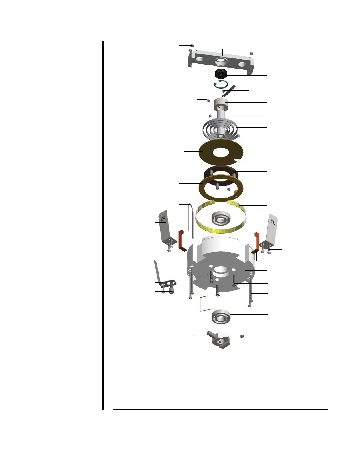
Support Shaft (#120-623)
1
2
Retainer, Internal, ¾" Bore
(# 120-629)
Contact Arm (#120-606)
Spring Adjuster Assembly
(#120-613)
Mechanical Stop (#120-627)
Contact Spring,
Black (#120-601)
Contact Spring,
Blue (#120-609)
6
8
5
Ground Cable
(#120-611)
Stop Arm Assembly
(#120-621)
Bushing (#120-626)
Spring Retainer
(#120-618)
Pivot Arm (#120-615)
Spring (#120-602)
Spring Adjuster Stand
Assembly (#120-617)
Resistor (#120-604)
Contact Spring,
Yellow (#120-605)
3
Contact Strip (#120-607)
Body (#120-603)
4
Bearing (#120-620)
7
1. WHS Nut, 4-40, "W ×"H, Qty. 4
2. #120-619 Screw, Phillips, Pan Head, 2-56 × .125L
3. #120-616 Set Screw, Hex, 6-32 × .1875L, Qty. 3
4. #120-610 Screw, Phillips, Pan Head, 4-40 × .375L, Qty. 5
5. #120-614 Screw, PHillips, Countersink, 6-32 × .75L, Qty. 3
6. WHS Screw, Phillips, Pan Head, 4-40 × 1.5L, Qty. 4
7. #120-608 Screw, Hex Socket, 10-32 × .5L
8. #120-622 Set Screw, Hex, 8-32 × .25L, Qty. 2
Insulation Plate (#120-612)
Appendix
Potentiometer Diagram