6 – Wiring and Electrical Connections
If the battery pack is not installed at delivery, proceed as follows:
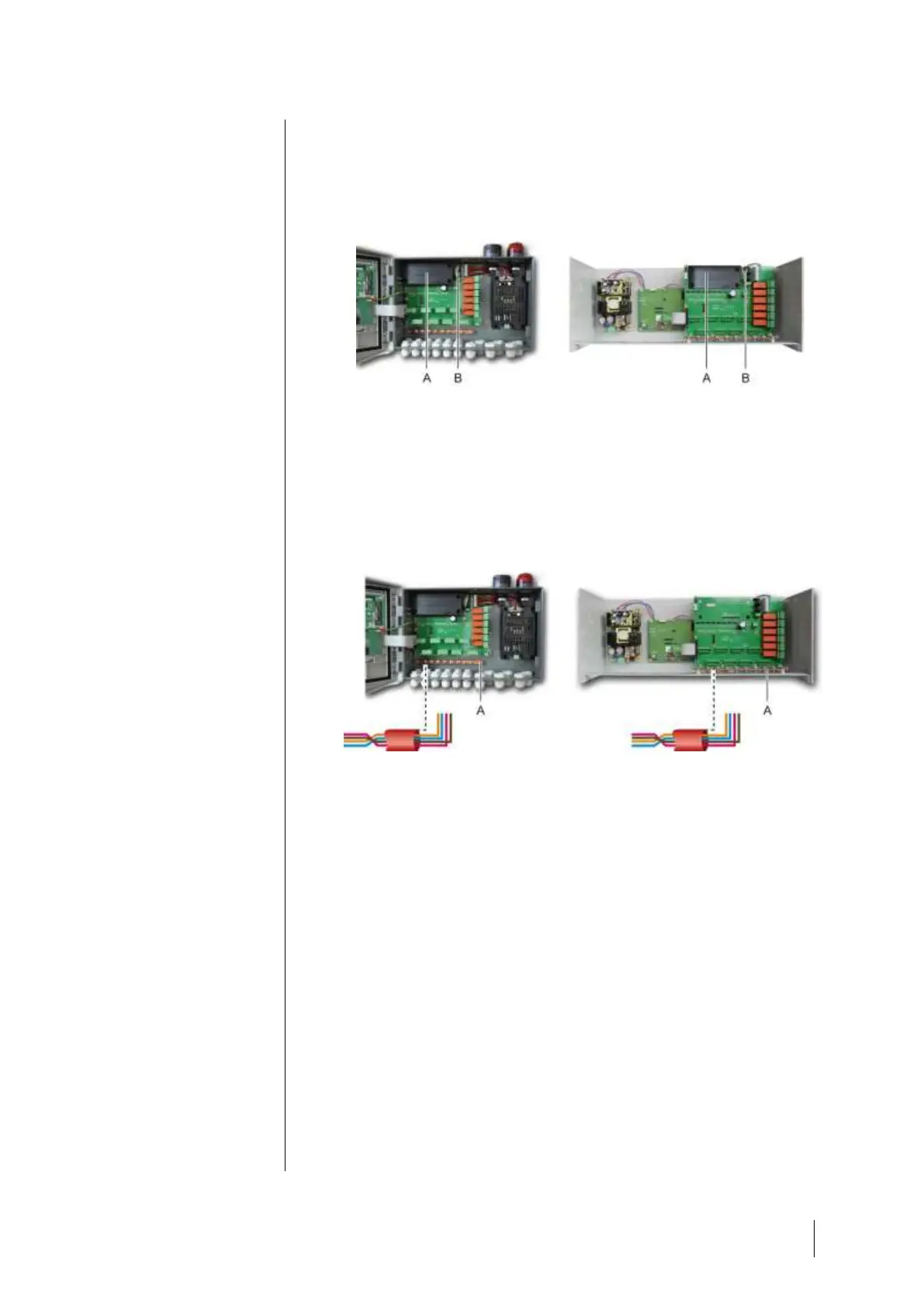
1. Position and fix the battery pack (A) at the place indicated using the 4
screws supplied.
2. Connect the battery pack connector to the connector (B) of the PCB. A
failsafe slot impedes any connection error.
Figure 30: Positioning the battery pack.
Earthing
The MX 43 is intended to be used in the parts of installations corresponding to
the category of overvoltage II and pollution degree 2 as per EN/IEC 60947-1.
In order to comply with this category of protection, it is absolutely necessary to
connect the ground terminal (Figure 31, A). Moreover, the cable braids of the
digital lines shall also be connected to this ground rod (Figure 31, A).
Figure 31: Ground connection through the ground rod.
Digital lines
The cabling of the digital lines connecting the controller to the different
modules deployed along the lines are the subject of the paragraphs
OLCT1ON Modules, 4- or 8-relay modules, 16-logic input modules, 8-analog
input modules and 4-analog output modules of this same chapter. It should be
remembered that this cable comes in 2 twisted pairs of 4 x 0.22 m² minimum,
type MPI-22A, nominal resistance of 120 Ohms.
Analog channels
For an analog 4-20mA detector connected directly on the MX 43 channels,
please connect the detector as shown below.
“I” is the 4-20mA signal, 0 and 24V correspond to the power supply.