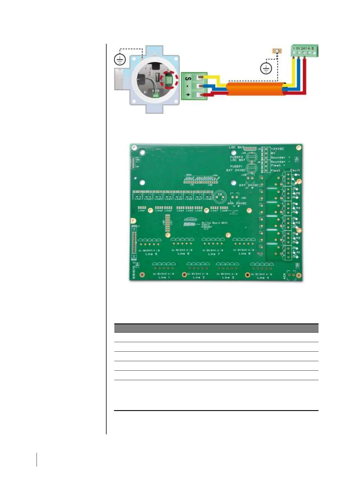
Figure 32: 4-20mA detector connected directly on the MX 43 channels.
Please see below the figure for the motherboard with position for channel
connection and relays.
Figure 33: MX 43 Motherboard.
Internal alarm relays
The MX 43 has 6 relays of the following internal alarms:
Relay of freely programmable function
Relay of freely programmable function
Relay of freely programmable function
Relay of freely programmable function
Relay of freely programmable function
Non-programmable common relay, energized, activated upon the presence of a
failure in the MX 43 (detector and/or module, increased internal temperature,
transition to power supply from the backup battery pack, system anomaly, etc.).
The deletion of this relay is automatic.
Table 10: Internal alarm relays.
MX 43
terminal
block for
channel
connexion