MAESTRO SMART 45
10.1.4 Technical data
10.1.4.1 Position of the connecting cable
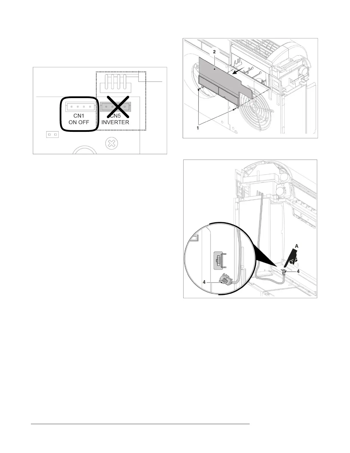
Connect the communication cable from the kit to connector CN1.
10.1.4.2 Selection of the interface installation position
The compartment in which the B1018 board is housed is in the upper
right.
– Disconnect the electrical power from the climate control unit.
– Remove the unit from the wall bracket.
– Loosen the body (Cf. 9.2 Body removal, on p. 32) in order to access
the housing (A) of the board.
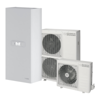
– Remove the screws (1) and the cover (2).
– Mount the B1018 board in its housing using the proper screws (3).
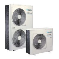
– Connect the communication cable to the serial port (4) located at the
bottom of the unit.