56
66 ASSEMBLY
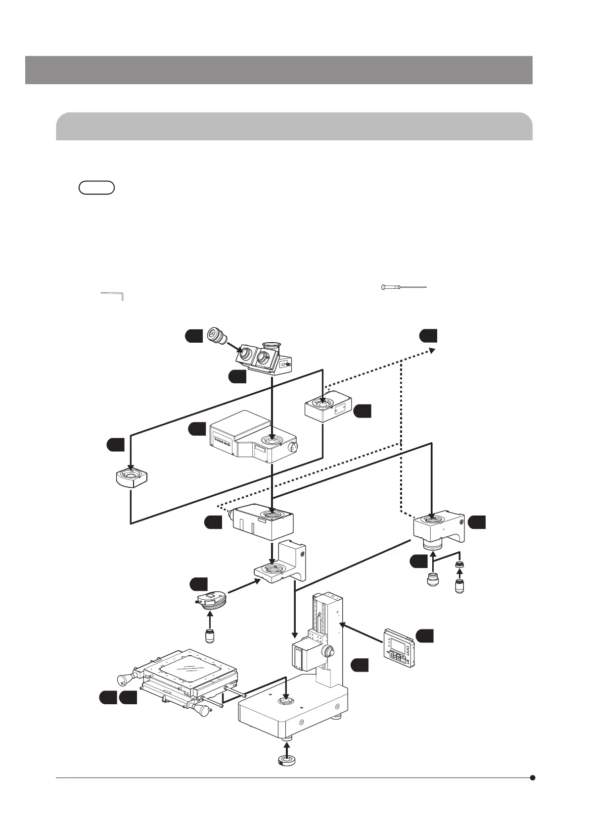
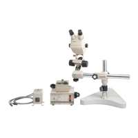
6-1 Assembly Diagram
Reflected light illuminator
MM6C-KMAS
MM6C-RLAS
Anti vibration plates
STM7-VI
Revolving nosepiece
• U-5RE-2
• U-D6RE
• U-5RES-ESD
• U-5BDRE
• U-D5BDRE
• U-D5BDRES-ESD
UIS2(UIS) brightfield
objective series
Autofocus unit
STM7-AF
Focus navigator unit
STM7-FN
Stage
• STM7-CS50
• STM7-CS100
• STM7-CS200
• STM7-CS300
Frame
• STM7-SF
• STM7-MF
• STM7-LF
• STM7-SFA
• STM7-MFA
• STM7-LFA
Eyepiece
MM6-OCC10X
MM6-OC10X
Observation tube
MM6-ETR
MM6-EMO
U-TLU
Reflected light fiber cable
Reflected light arm
MM6C-VL
Objective
conversion adapter
BD-M-AD
UIS2 (UIS) brightfield
objective series
Digital indicator
STM7-DI
Objective
MM6-OB
series
11
11
8
5
13
7
6
4
10
3
1
2
9
The diagram below shows the sequence of assembly of the various modules.
The numbers indicate the order of assembly. The modules shown in the following diagram are merely the basic ones. For
the modules which are not shown in the diagram, please consult your Olympus representative or the latest brochures.
· The assembly and adjustments are performed by the Olympus dealer. As other tools than those provided
with instrument are necessary, the dealer should prepare them.
· In the following conditions, attach the anti vibration plates STM7-VI (option) to the microscope.
· When installing the microscope in an area with frequent vibration.
· When installing the microscope on a table with a thin top board. (Basically, prepare a table with a
thick top board.)
· When assembling the microscope, make sure that all parts are free of dust and dirt, and avoid scratching
any parts or touching glass surfaces. Also be sure to release the transport lock of the focusing unit and
stage by removing the screws before use (see page 58 or 61).
} All assembly operations are possible by using the 3 mm Allen screwdriver (
) and 4 mm Allen wrench (
) provided with the frame, control box or stage.
} After the assembly is completed, input the setting values of the microscope. (page 74)
12
Eyepoint
adjuster
U-EPA2