62
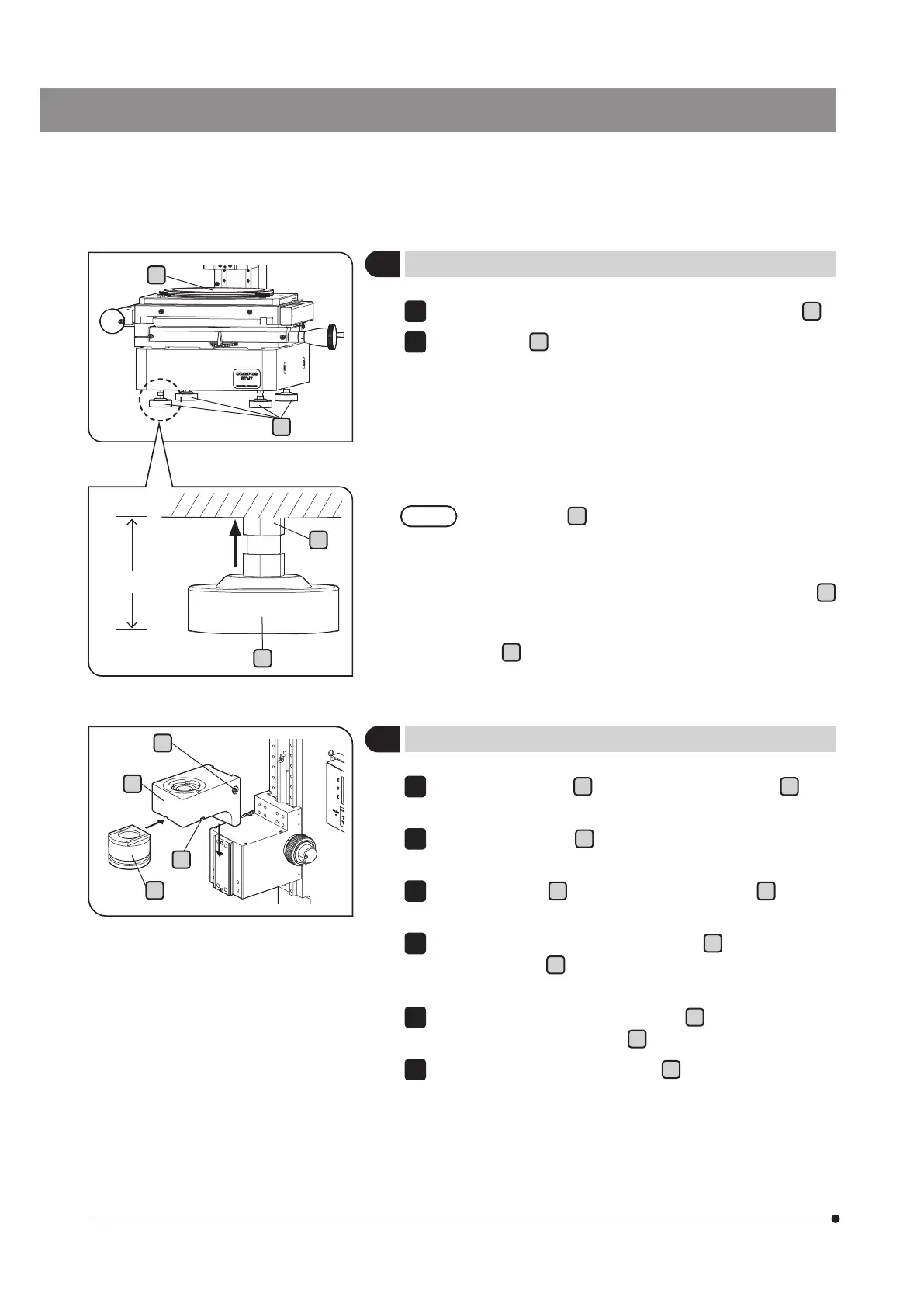
Place the level provided by the sales office on the stage glass
g
.
Adjust the legs
h
(2 each on front and back) of the frame to level
front/back/right/left by using the spanner.
When the X-axis or Y-axis clutch is released with the stage position as a
center position, make sure that the stage does not move spontaneously
in either X or Y direction.
} When the microscope is assembled after completing the setup of
the camera, etc., perform the leveling again.
· Adjust the legs
h
of the frame within the range of 50 mm
or less from the bottom surface of the frame.
If adjusting the legs exceeding this range, the microscope
may be overturned.
· When adjusting the legs of the frame, loosen the fixing nuts
i
shown at the upper area in the picture on the left.
· After the legs are adjusted, be sure to tighten the fixing
nuts
i
shown at the upper area in the picture on the left
completely until it touches the bottom surface of the frame.
1
2
4
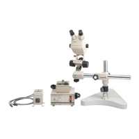
Leveling the stage
g
h
5
Mounting the brightfield reflected light arm (MM6C-VL)
Fully loosen the clamp
b
(stud) of the reflected light arm
a
using
the Allen screwdriver provided with the frame.
Fit the reflected light arm
a
into the mount dovetail on the frame all the
way until it is stopped. Take care that the reflected light arm is not tilted.
Tighten the clamp
b
(stud) of the reflected light arm
a
using the
Allen screwdriver provided with the frame.
Fully loosen the objective seat mount screw
c
on the right of the
reflected light arm
a
using the Allen screwdriver provided with the
frame.
Fit the mount dovetail of the objective seat
d
into the objective seat
mount on the reflected light arm
a
all the way until it is stopped.
Tighten the objective seat mount screw
c
using the Allen screwdriver
provided with the microscope frame.
1
2
3
4
5
6
b
a
c
d
50 mm or less
i
h
Bottom surface of the frameBottom surface of the frame
Tightening
direction
Legs of the frame