70
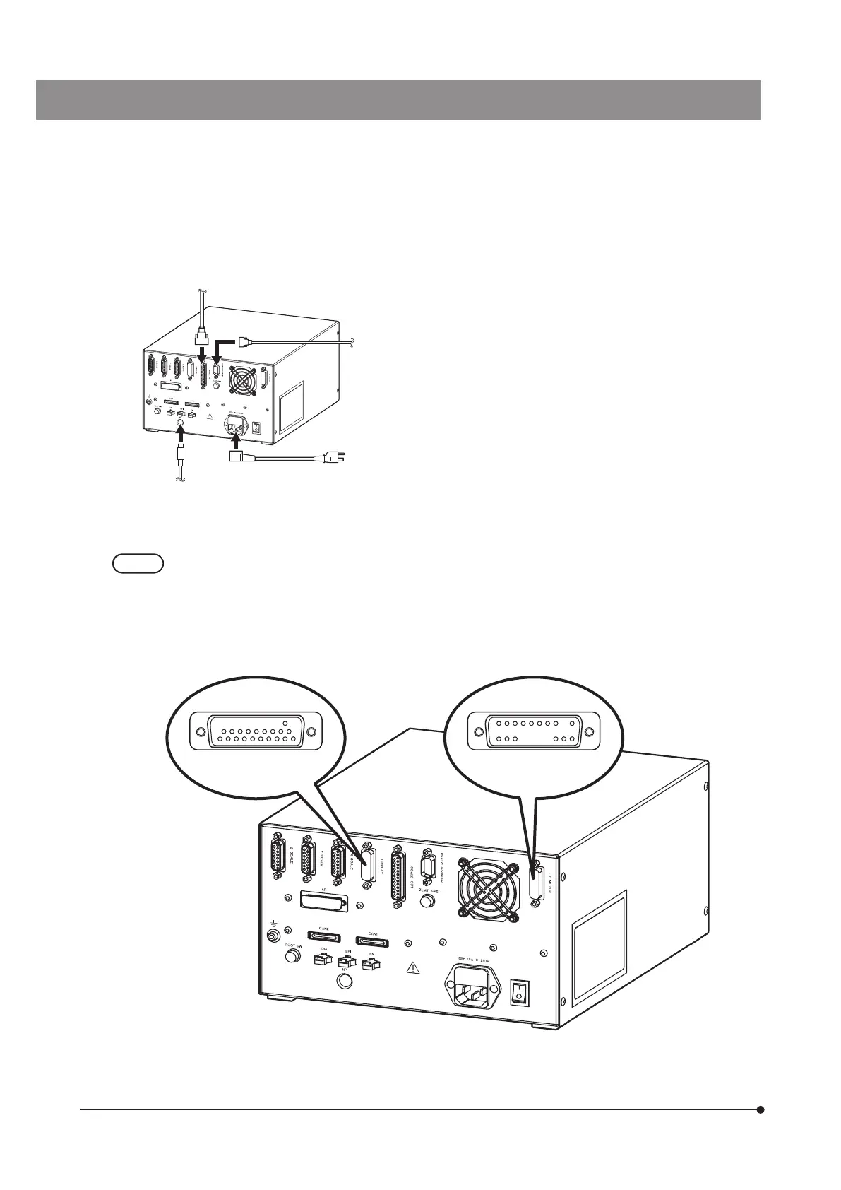
Power cord
Control box
STM7-CB/STM7-CBA
External processing device (DSUB25Pin Female)*
} If no instruction is specified to the
connector, the cables from the frame,
stage or other modules are connected.
} For connections of positions with *
mark, contact Olympus for details.
· Controller
· Printer (DSUB9Pin Male)*
Coded quintuple
revolving nosepiece
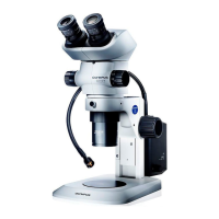
· When connecting DISPLAY of the control box with the digital indicator, check the pin positions of the
connector of the cable for digital indicator.
· When connecting Z-MOTOR of the control box with the motorized frame, check the pin positions of the
connector of the cable for motorized frame.
} Since the length or the shape of cables is similar, distinguish them by the pin positions of the connector.
Connector of cable for
digital indicator
Connector of cable for
motorized frame