Switch Bar Temperature Option
With Pulse Interpolation and when using piston-type provers, the switch bar temperature
accounts for the effect of expansion or contraction the temperature has on the distance between
the optical detector switches located on the switch bar.
In most cases, Pulse Interpolation prover detector switches are not positioned in the prover flow
tube; they are mounted externally. The distance between the optical detector switches
determines the prover volume. A spacing rod (also known as a switch bar or invar rod) separates
these optical detector switches by a precise distance. Ambient temperature variations cause the
switch bar to expand or contract, which requires adjustments to the prover water draw volume.
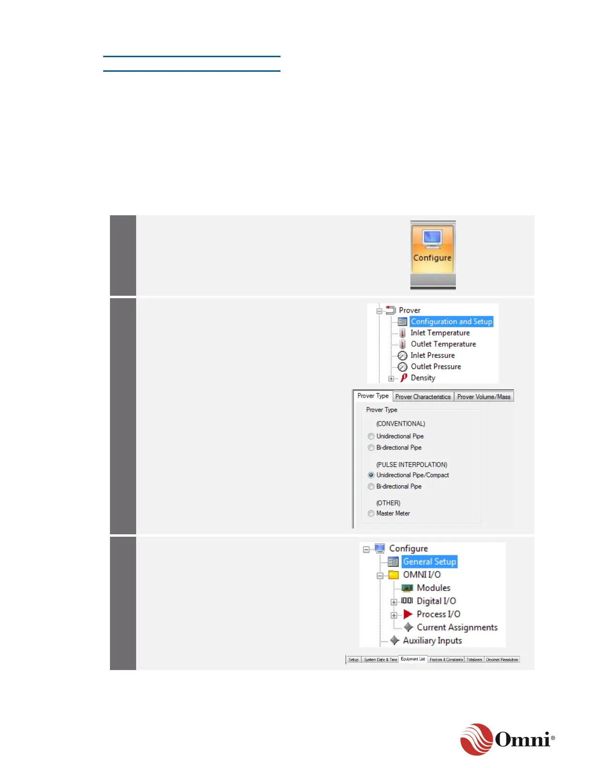
To set up the switch bar temperature option, follow these instructions:
a. Expand the Prover function in the
Configure tree.
b. Select Configuration and Setup.
c. Verify that a Pulse Interpolation type
prover is selected in the Prover Type
screen.
 Loading...