© 2011 Omnicell, Inc. External Return Bin Installation and Service Guide/67-2038 Rev D
Service 3-5
Printed Circuit Board (PCB)
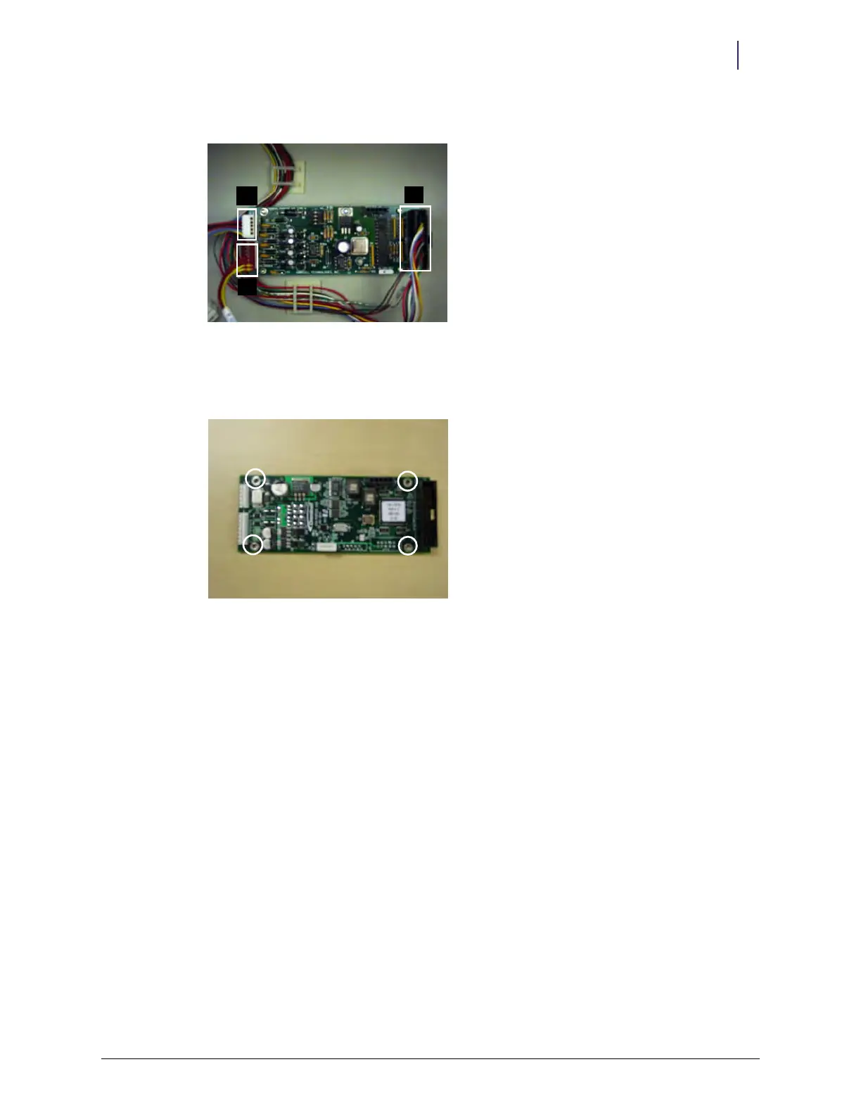
5. Disconnect J1, J2, and J3 connectors.
Figure 3-10. J connector locations
6. Remove the four 4-40 SOC screws.
7. Replace the PCB.
Figure 3-11. Screw locations
8. Secure the new PCB with the 4-40 SOC screws.
9. Maneuver the metal mount back into position.
10. Tighten the two nuts on either side of the plate.
11. Close the return door.
12. Lock up the ERB.
J3J1
J2