RX Quick Start Guide
14 RX Quick Start Guide
2.8 Digital inputs SINK/SOURCE (NPN/PNP) settings
3 PROGRAMMING RX
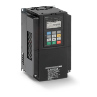
3.1 Digital operator
The display is used in programming the inverter's parameters, as well as monitoring specific parameter values during operation
Sinking internal supply (for NPN outputs) Sinking external supply (for NPN outputs)
Sourcing internal supply (for PNP outputs) Sourcing external supply (for PNP outputs)
Item Content of Display Content
Display Mode MONITOR-A Monitor-A mode
MONITOR-B Monitor-B mode
FUNCTION Function mode
TRIP Trip (error) mode
WARNING Warning mode (Alarm)
OPTION LCD Configuration Mode
Motor selected M1 Motor 1 (SET multifunction = OFF)
M2 Motor 2 (SET multifunction = ON)
Inverter RUN Status STOP Stopped
FWD Forward running
REV Reverse running
Display Selection (b037) ALL Display all
UTL Function individual display
USR User setting display
CMP Data compare display
BAS Basic display
P24+V
PLC
CM1
FW
8
24 V DC
Inverter
Short-circuit
bar
COM
Output unit etc.
P24+V
PLC
CM1
FW
8
24 V DC
Inverter
COM
DC24V
Output unit etc.
P24
PLC
CM1
FW
8
0V
Output unit etc.
24 V DC
Inverter
Short-circuit
bar
COM
P24
PLC
CM1
FW
8
0V
Output unit etc.
24 V DC
Inverter
COM
24 V DC
 Loading...


