EasyManua.ls Logo

Omron CP1E - INTRODUCTION User Manual

Omron CP1E - INTRODUCTION
182 pages
To Next Page IconTo Next Page
To Previous Page IconTo Previous Page
Page #106 background imageLoading...
Page #106 background image
A
Appendix
A-1 Channel/Relay Numbers
104 SYSMAC CP1L/CP1E Introduction Manual
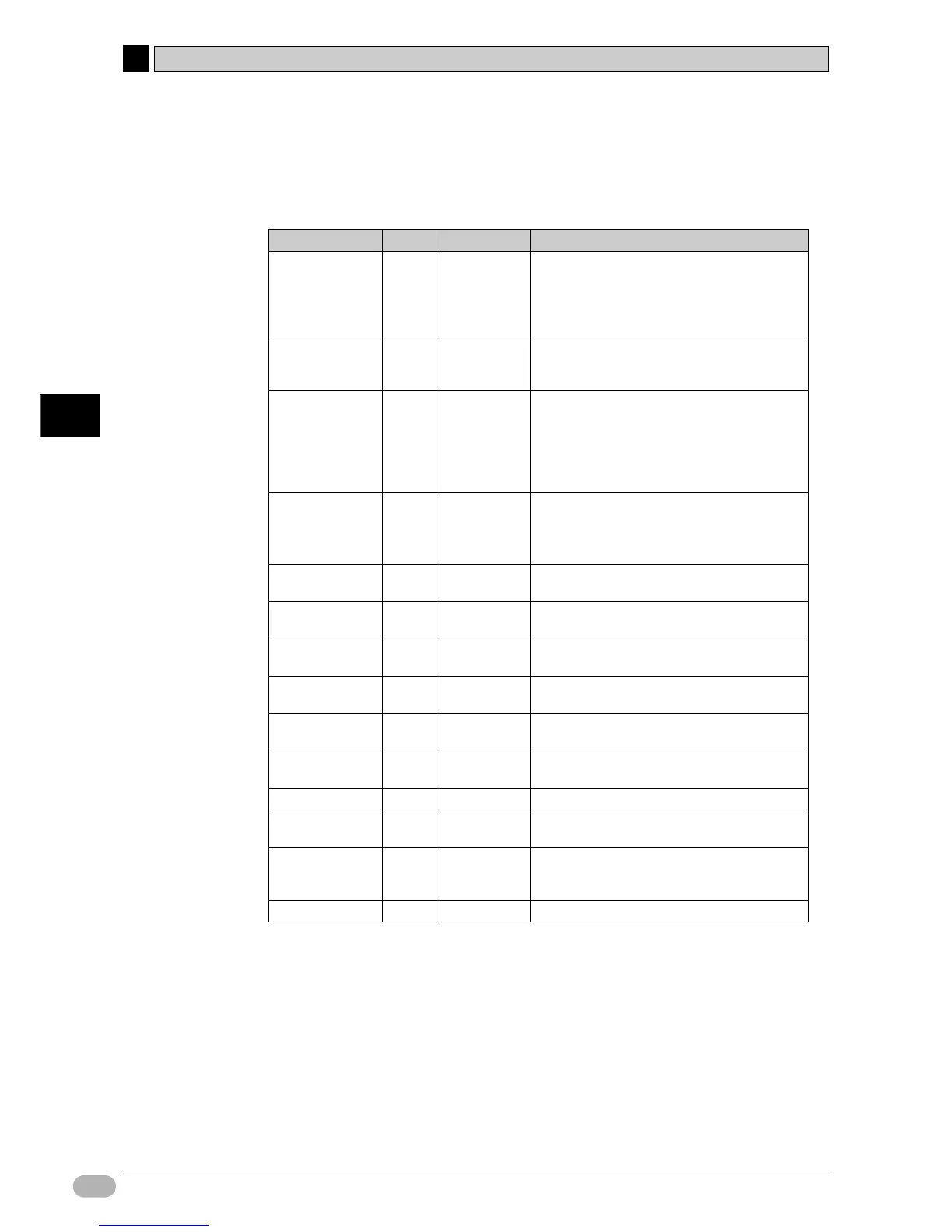
Condition Flags
Condition flags are used to reflect the processing results during or after the
execution of instructions. Whether a flag is used or not will depend on the
instruction. These flags are used in ladder programs as contacts.
Name Label In CX-P Function
Error flag ER P_ER
Turns ON when an instruction handling BCD
data attempts to execute using non-BCD data.
Turns ON when an operand value specified by
the instruction is invalid (e.g. a value outside
the work area).
Access error flag AER P_AER Turns ON when unauthorized access is
attempted on an area that is not meant to be
accessed.
Carry flag CY P_CY
Turns ON when the number of digits is
increased or decreased as a result of
executing an arithmetical instruction.
Data shift instructions and some arithmetical
instructions may handle the carry as part of
their processing.
Equals flag
=
P_EQ
Turns ON when data comparison returns an
"equal".
Turns ON when data becomes 0 as a result of
calculations or transfers.
Unequal flag
< >
P_NE Turns ON when data comparison returns an
"unequal".
Greater than flag
>
P_GT Turns ON when data comparison returns
"data1>data2".
Greater than or
equals flag
>=
P_GE Turns ON when data comparison returns
"data1>=data2".
Less than flag
<
P_LT Turns ON when data comparison returns
"data1<data2".
Less than or
equals flag
<=
P_LE Turns ON when data comparison returns
"data1=<data2".
Negative flag
N P_N Turns ON when the MSB becomes 1 as a result
of calculations.
Overflow flag OF P_OF Turns ON when the calculation result overflows.
Underflow flag UF P_UF Turns ON when the calculation result
underflows.
Always ON flag ON P_ON Remains ON at all times. Used as an execution
condition for instructions that cannot be
connected directly to the bus bar.
Always OFF flag OFF P_OFF Remains OFF at all times.

Table of Contents

Question and Answer IconNeed help?

Do you have a question about the Omron CP1E - INTRODUCTION and is the answer not in the manual?

Omron CP1E - INTRODUCTION Specifications

General IconGeneral
SeriesCP1E
ManufacturerOmron
Input Voltage100 to 240 VAC or 24 VDC (depending on model)
I/O Points10 to 60 points
Number of Inputs6 to 36 points
Number of Outputs4 to 24 points
Communication PortsUSB, RS-232C
Programming LanguageLadder Diagram (LD)
Power Supply100-240V AC or 24V DC
Storage Temperature-25°C to 65°C
Vibration Resistance10 to 57 Hz, 0.075mm amplitude
Shock Resistance147 m/s², 3 times each in X, Y, Z directions
WeightVaries by model
TypeProgrammable Logic Controller (PLC)

Summary

Introduction and Preliminary Information

Precautions and Safety Guidelines

Details essential precautions, intended audience, safety measures, and application guidelines for safe operation.

Section 1: CP1L/CP1E Overview

Section 2: Designing Systems

Section 3: Mounting and Wiring

Section 4: Creating Programs

Ladder Program Creation Process

Explains how to construct ladder programs for the shutter control system example.

Using CX-Programmer Software

Covers starting and navigating the CX-Programmer software interface for program development.

Inputting and Editing Program Elements

Step-by-step guide to entering ladder logic elements and modifying comments and rungs.

Section 5: Transferring and Debugging Programs

Establishing Online Connection

Describes establishing a connection between the computer and CP1L for program transfer and monitoring.

Program Transfer and Execution

Step-by-step process for transferring programs from CX-Programmer to CP1L and executing them.

Online Adjusting and Debugging Techniques

Covers monitoring, force-setting, searching, and online editing for efficient debugging.

Related product manuals