3
SYSMAC CP1L/CP1E Introduction Manual 35
3-3 Wiring Devices
3
Mounting and Wiring
• In consideration of voltage drops and allowable current, use the thickest
electrical wire possible.
(2) LG
LG is a functional ground terminal (noise-filtered neutral terminal). To
resolve errors and electrical shocks caused by noise, short the LG and GR
terminals for a class D grounding (ground resistance of 100 or less).
(3) GR
GR is a protective ground terminal. To prevent electrical shocks, use a
dedicated ground line (2mm
2
or thicker) for a class D grounding (ground
resistance of 100 or less).
• To prevent electrical shocks and noise, always ground the terminal with
class D grounding (ground resistance of 100 or less).
• If the power supply has a grounded phase, connect the grounded phase to
the L2/N terminal.
• Do not share the ground line with other equipment, or connect it to building
structure beams. The results may be unfavorable.
(4) Recommended crimp terminal
When wiring the AC power supply, use ring-type crimp terminals to prevent
unintended disconnection.
WARNING Secure the AC power supply line to the terminal block with 0.5N·m of torque.
Loosening the screw may result in a fire or malfunction.
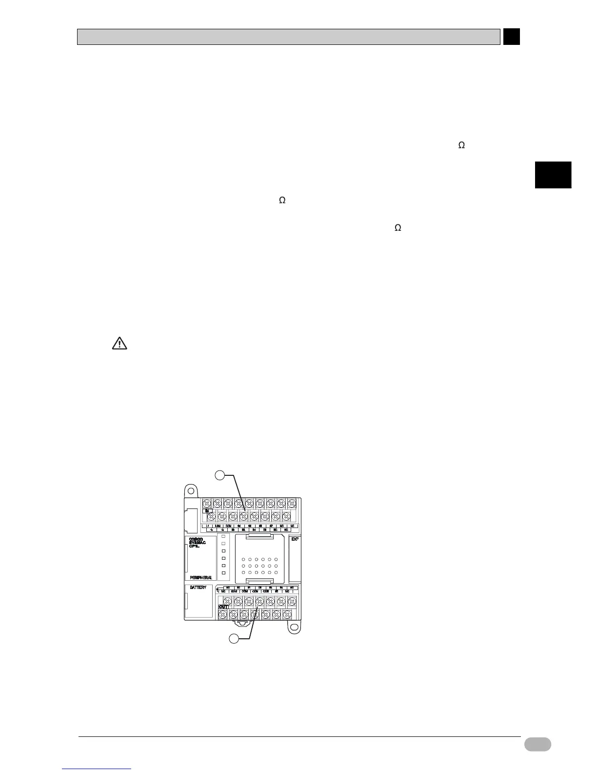
3-3-2 Connecting I/O Lines
■14-point I/O Units
CP1L has input terminals located at the top, and output terminals located at the
bottom.
(1) Input terminal
(2) Output terminal
1
2