3
36 SYSMAC CP1L/CP1E Introduction Manual
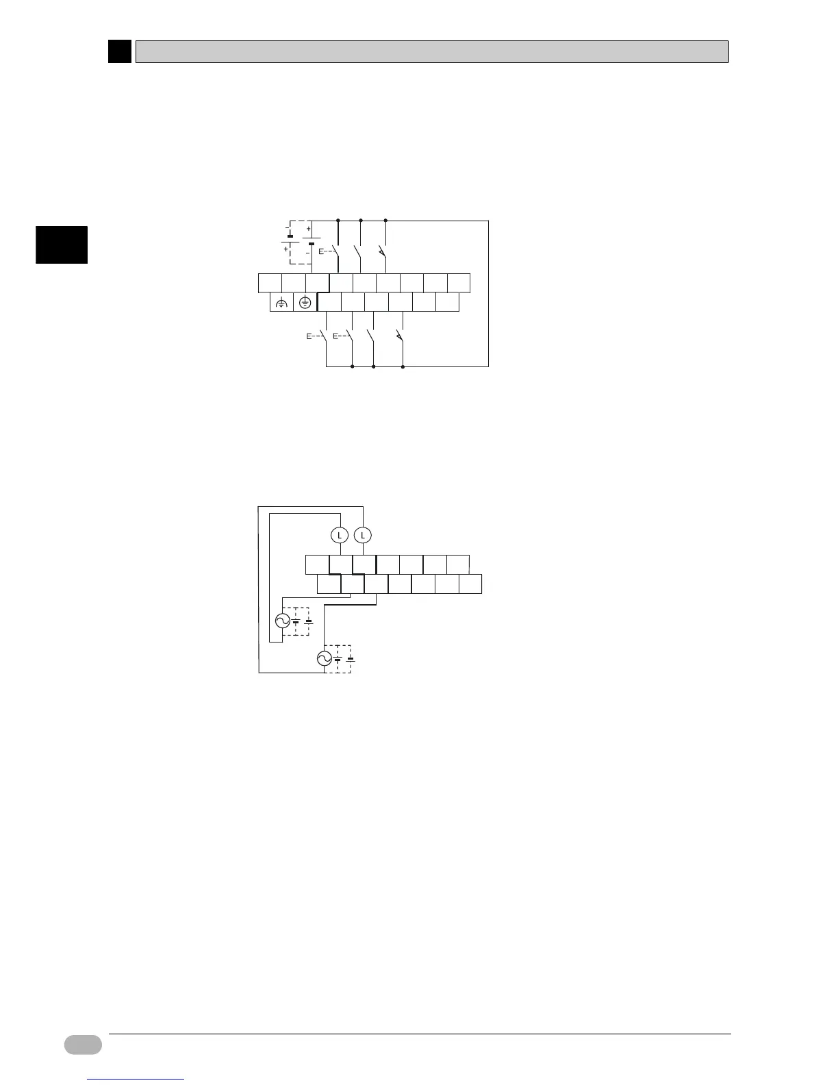
3-3 Wiring Devices
3
Mounting and Wiring
●Wiring Inputs
1. Wire the inputs as shown, while referring to 2-3 I/O Allocation for the
Shutter Control System.
●Wiring Outputs
1. Wire the outputs as shown, while referring to 2-3 I/O Allocation for the
Shutter Control System.
For details on wiring, refer to 3-5-4 I/O Wiring for CPU Units with 14 I/O Points
of CP Series CP1L CPU Unit User’s Manual (W462) or 5-3-3 I/O Wiring of CP
Series CP1E CPU Unit Hardware User's Manual (W479).
L1 L2/N COM 01 03 05 07 NC
00 02 04 06
PB1
(0.00)
PB2
(0.01)
PB3
(0.02)
SEN1
(0.03)
SEN2
(0.04)
LS1
(0.05)
LS2
(0.06)
NC
NC
NC
+ 00 01 02 03 04
-05
MO2
(100.01)
MO1
(100.00)
NC
NC
COM
COM
COM
COM