EasyManua.ls Logo

Omron CP1E - INTRODUCTION User Manual

Omron CP1E - INTRODUCTION
182 pages
To Next Page IconTo Next Page
To Previous Page IconTo Previous Page
Page #47 background imageLoading...
Page #47 background image
4-2 Creating Ladder Programs
4
4
SYSMAC CP1L/CP1E Introduction Manual 45
Creating Programs
4-2 Creating Ladder Programs
A ladder program can now be created for the example introduced in SECTION 2 System Design. First,
however, the functions of the ladder program will be described.
4-2-1 Operation
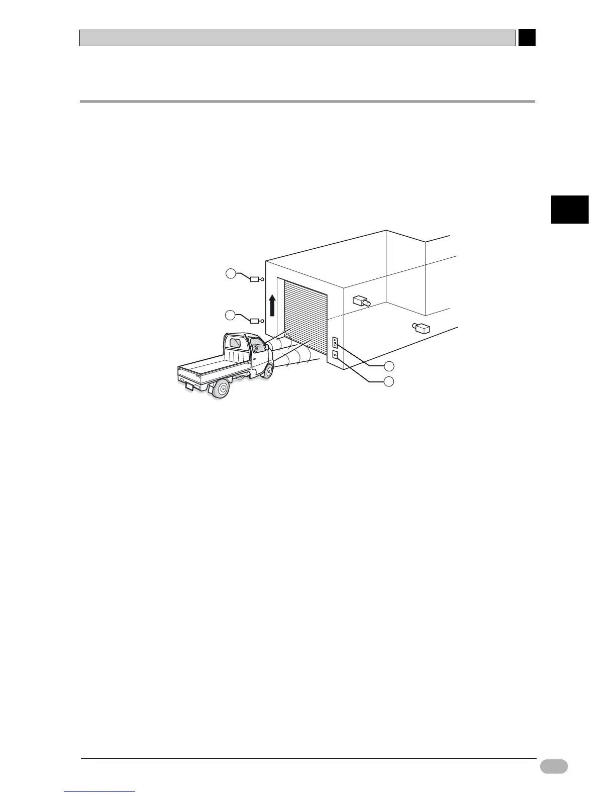
The ladder program to be created will open and close a garage shutter.
For details on the example application, refer to 2-2-1 Operation.
Entering the Garage
The component functions and operations will be defined in detail below.
(1) Push-buttons (A16-series, etc):
The shutter can be opened, closed, and stopped with buttons.
The OPEN and CLOSE buttons will continue operating the shutter even when
they are not held down. A self-maintaining bit is used to achieve this.
(2) Limit switches (WL/WLM-series, etc):
When the shutter is fully opened or fully closed, it will be stopped by a limit
switch.
When the shutter is opening, the de-escalation motor will be interlocked to
prevent damage.
(3) Light detection sensor:
A light detection sensor detects light from headlights pointed at the garage.
When 3 headlight flashes are detected by a counter instruction, the shutter
escalation motor is activated.
After the first headlight flash, a timer is activated by a timer instruction. After 5
seconds, a reset command is given to the counter instruction.
The present value of the counter instruction is retained even when CP1L is
powered OFF. To prevent malfunction, a reset command is given to the
counter instruction when CP1L is powered ON.
1
2
2
3

Table of Contents

Question and Answer IconNeed help?

Do you have a question about the Omron CP1E - INTRODUCTION and is the answer not in the manual?

Omron CP1E - INTRODUCTION Specifications

General IconGeneral
SeriesCP1E
ManufacturerOmron
Input Voltage100 to 240 VAC or 24 VDC (depending on model)
I/O Points10 to 60 points
Number of Inputs6 to 36 points
Number of Outputs4 to 24 points
Communication PortsUSB, RS-232C
Programming LanguageLadder Diagram (LD)
Power Supply100-240V AC or 24V DC
Storage Temperature-25°C to 65°C
Vibration Resistance10 to 57 Hz, 0.075mm amplitude
Shock Resistance147 m/s², 3 times each in X, Y, Z directions
WeightVaries by model
TypeProgrammable Logic Controller (PLC)

Summary

Introduction and Preliminary Information

Precautions and Safety Guidelines

Details essential precautions, intended audience, safety measures, and application guidelines for safe operation.

Section 1: CP1L/CP1E Overview

Section 2: Designing Systems

Section 3: Mounting and Wiring

Section 4: Creating Programs

Ladder Program Creation Process

Explains how to construct ladder programs for the shutter control system example.

Using CX-Programmer Software

Covers starting and navigating the CX-Programmer software interface for program development.

Inputting and Editing Program Elements

Step-by-step guide to entering ladder logic elements and modifying comments and rungs.

Section 5: Transferring and Debugging Programs

Establishing Online Connection

Describes establishing a connection between the computer and CP1L for program transfer and monitoring.

Program Transfer and Execution

Step-by-step process for transferring programs from CX-Programmer to CP1L and executing them.

Online Adjusting and Debugging Techniques

Covers monitoring, force-setting, searching, and online editing for efficient debugging.

Related product manuals