3
34 SYSMAC CP1L/CP1E Introduction Manual
3-3 Wiring Devices
3
Mounting and Wiring
3-3 Wiring Devices
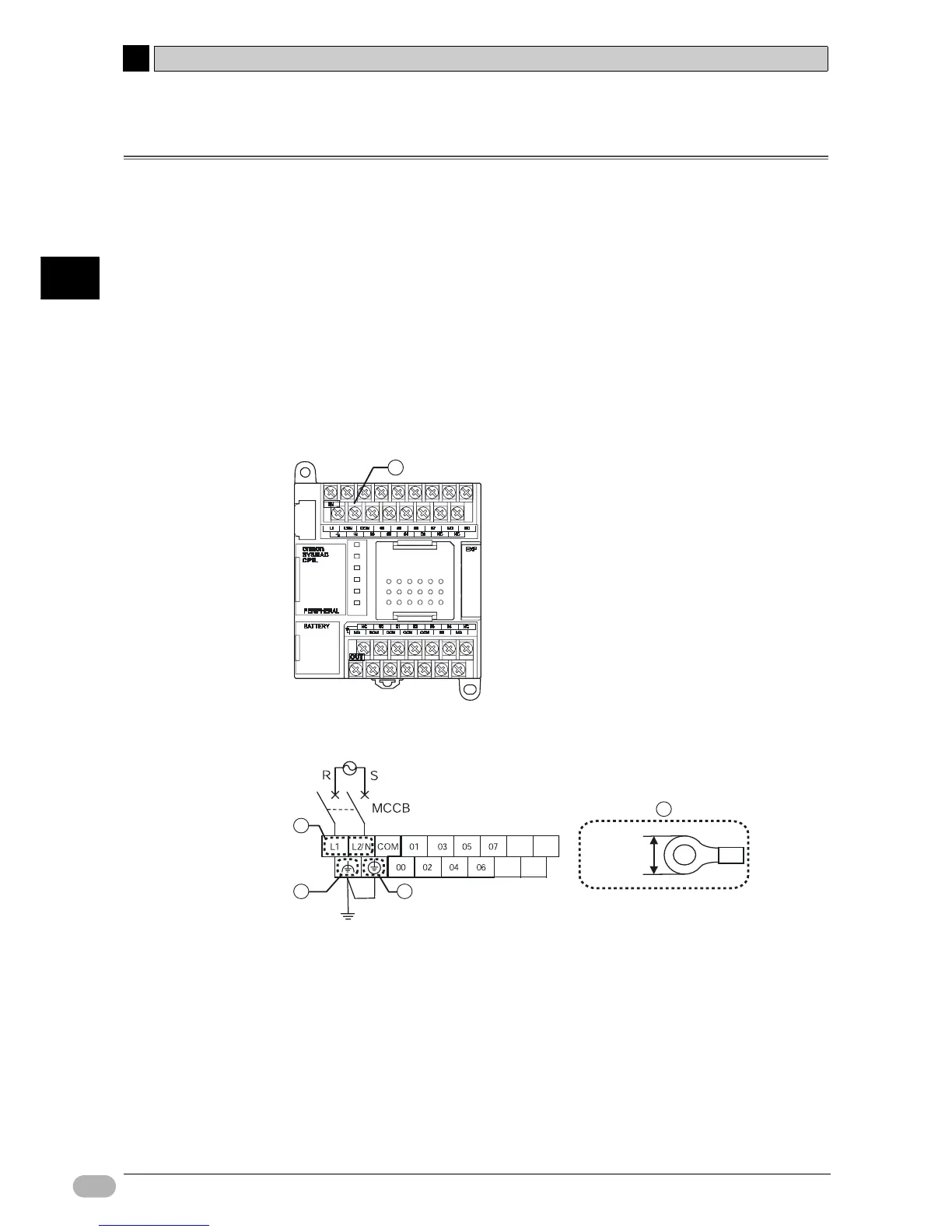
This section explains how to wire CP1L (14-point I/O unit with AC power supply).
■Protective Label
Wire scraps may be scattered during wiring. To prevent them from entering the
unit, leave the protective label (adhered on the top surface of the unit) on until
wiring is done.
When wiring is complete, remove the label to ensure proper heat dissipation.
3-3-1 Connecting Power Supply and Ground Lines
This section explains how to wire the power and ground lines.
■Units with AC Power Supply
Power and ground terminals (A) are located near the top of CP1L.
Terminal block layout at (A)
(1) Power supply terminal
Supply 100 to 240VAC voltage at 50/60Hz.
The acceptable supply voltage range is 85 to 264VAC.
• Use separate circuits for the power supply circuit and the motor circuit, in
order to prevent voltage drops due to starting currents and inrush currents
from other equipment.
• Use a twisted-pair of power supply cables to prevent noise from the power
supply line. Adding a 1:1 isolating transformer will further reduce electrical
noise.
A
NC
NC
NC
NC
6.2mm max.
1
2
3
4