A
Appendix
A-4 CP1L Programming Examples
SYSMAC CP1L/CP1E Introduction Manual 157
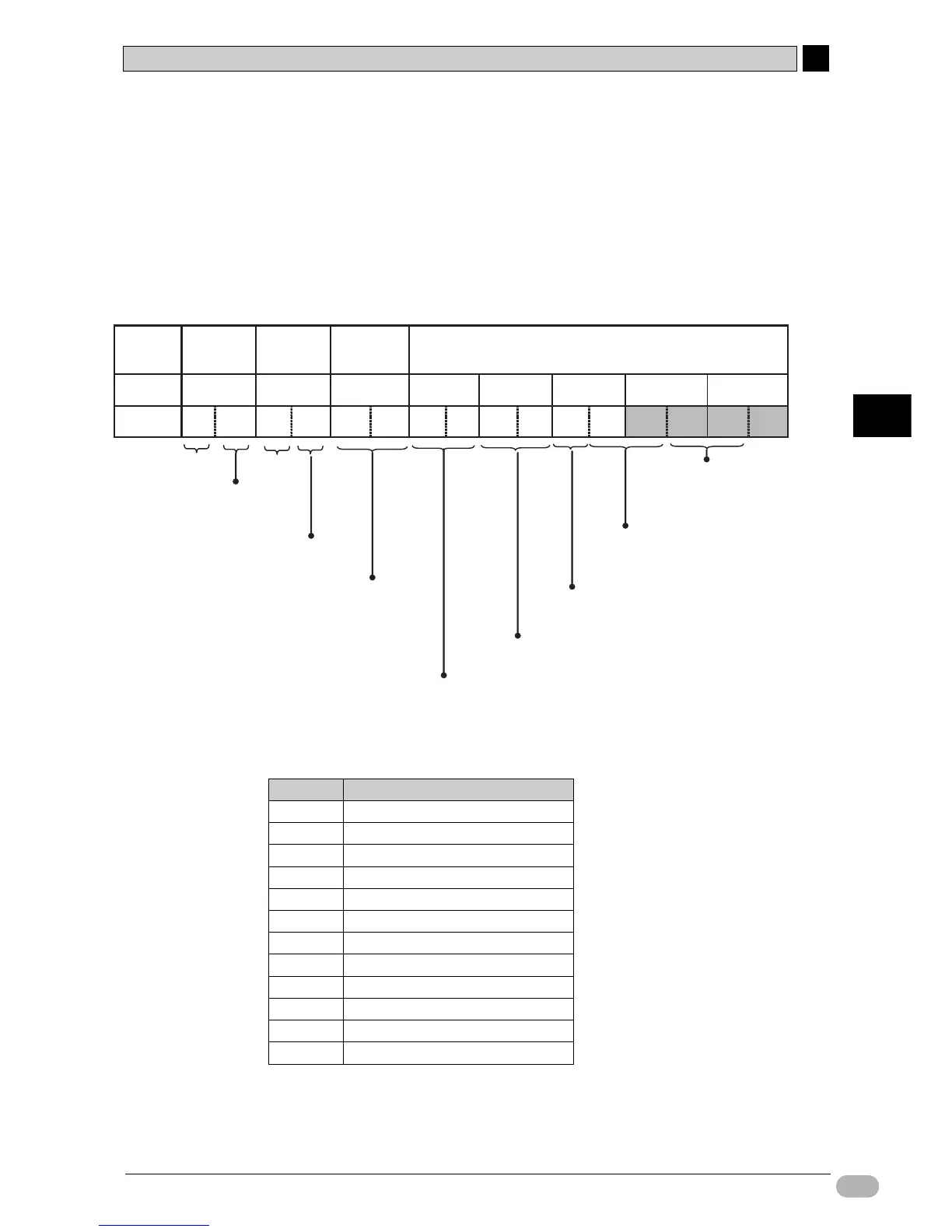
●DM Area Setup
• DM Fixed Allocation Words for Modbus-RTU Easy Master
DM settings from D32300 to D32305 (CP1E: D1201 to D1205) are set before the
execution of the ladder program.
D32306 and D32307 (CP1E: D1206 and D1207) do not need to be set explicitly.
They are modified by MOV instructions, and are used to change, start, and stop
frequency commands.
• Operation Command (Register No.0001 Hex) allocation and details for
Inverter V1000
For this example, only operation command (No.0 bit) will be used.
• With Modbus-RTU easy master function, CRC-16 checksums do not need to be
set in the DM area, since they are calculated automatically.
00
D3230
4
(CP1E: D1204)
0100
D32303
(CP1E: D1203)
0900
D32302
(CP1E: D1202)
1000
D32301
(CP1E: D1201)
01
00
D32300
(CP1E: D1200)
02
01
D32306
(CP1E: D1206)
0004
D32305
(CP1E: D1205)
02
58
D32307
(CP1E: D1207)
02 58
Communication data: D32303 to Max. D32349
(CP1E: D1203 to Max. D1249)
FUNCTION
code
Address
00
00
Number of registers data is written to: 2
(2 data: No.0001 and No.0002 on register 2)
Communication
data bytes
Slave
address
Setting
Value
Inverter slave address: 1 (Hex)
Inverter data write: 10 (Hex)
For number of bytes, use 9 bytes from
upper D32303 to upper D32307
(CP1E: Upper D1203 to upper D1207)
Serial Port 1: Command
Register No. for starting data write:0001
(start writing to inverter at register No.0001)
Attached data size in bytes: 4
(4 bytes from lower D32305 to upper D32307
(CP1E: lower D1205 to upper D1207))
Data for starting register
(e.g. set 0001 Hex for No.0001
[operation command (see below)])
Data for next register
(e.g. set 60.0Hz (0258 Hex) for No.0002
[frequency command])
Bit No. Setting
0 Operation command (1: Start)
1 Normal/reversed rotation (1: Reversed)
2 External error (1: EF0)
3 Error reset (1: Error reset)
4 Multifunction input 1 (1: ON)
5 Multifunction input 2 (1: ON)
6 Multifunction input 3 (1: ON)
7 Multifunction input 4 (1: ON)
8 Multifunction input 5 (1: ON)
9 Multifunction input 6 (1: ON)
A(Unused)
B to F (Unused)