19
Wiring Terminals Section 2-2
• The following table shows the specifications for each output type.
• The voltage output (control output) is not electrically insulated from the
internal circuits. When using a grounding thermocouple, do not connect
the control output terminals to the ground. If the control output terminals
are connected to the ground, errors will occur in the measured tempera-
ture values as a result of leakage current.
Alarm output/Control
output 2
• On the E5@Z-@3@@, alarm output 1 (ALM1) is across terminals 5 and 6,
and alarm output 2 (ALM2) is across terminals 4 and 6, and alarm output
3 (ALM3) is across terminals 3 and 6. When heating/cooling control is
used, alarm output 3 becomes cooling output.
When the input error output is set to “ON”, alarm output 1 turns ON when
an input error occurs.
• Terminals 5 and 6 on the E5AZ/E5EZ to which an E53-AZH Option Unit is
mounted output the alarm output 1 or heater burnout alarm values. If the
mode of alarm output 1 is set to 0 to disable alarm output 1, terminals 5
and 6 will output the heater burnout alarm.
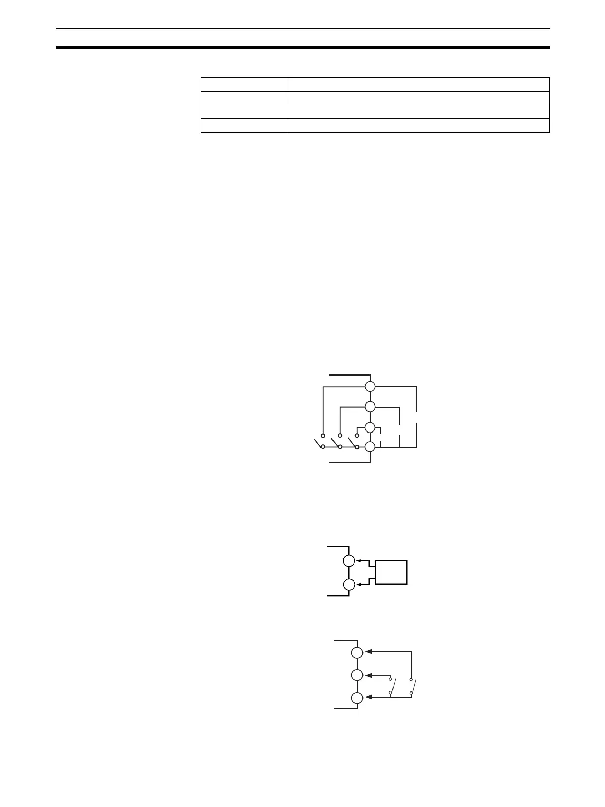
• The equivalent circuits of alarm output 1, 2, and 3 are shown in the follow-
ing diagram.
• Relay specifications are as follows:
SPST-NO 250 VAC 2 A
CT input • When the option unit (E53-AZH) is mounted on the E5AZ/E5EZ and the
heater burnout function is used, connect a current transformer (CT)
across terminals 15 and 16.
Event input • When the option event input unit E53-AZB is mounted in the E5AZ/E5EZ
and event input is used, connect to terminals 12 to 14.
• Use event inputs under the following conditions:
Output type Specifications
Relay 250 VAC, 5 A (resistive load), electrical life: 100,000 operations
Voltage (PNP) PNP type, 12 VDC, 40 mA (with short-circuit protection)
Current 4 to 20 mA DC, load: 600 Ω max., resolution: approx. 2,600
3
4
5
6
AL1/HB
AL2
AL3/OUT
15
16
CT
12
13
EV1
EV2
14
+
+
−