61
F3SJ-B
User’s Manual
Chapter3 Mounting
Wiring/Installation
E
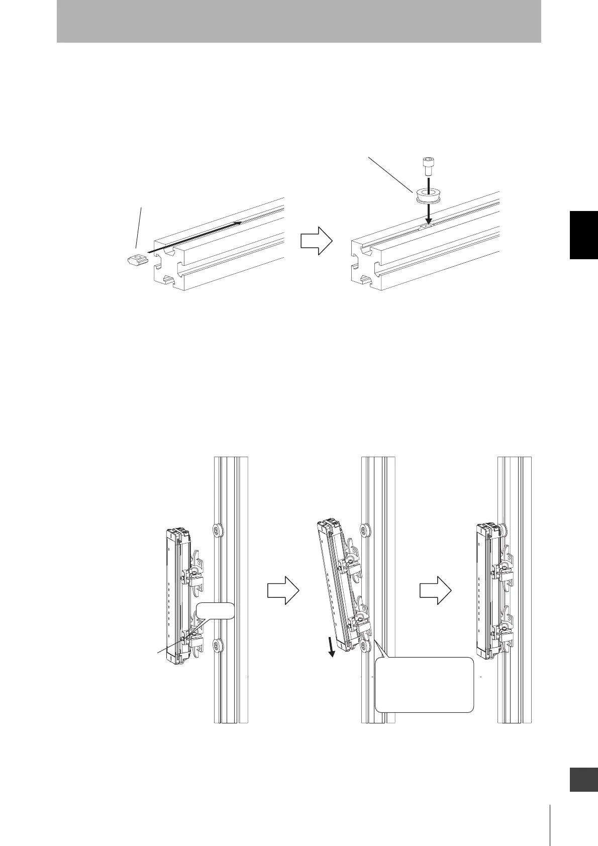
3. Mount One-touch M6 Brackets (or M8 Brackets) to the aluminum profile according to the position
where the sensor is mounted. The positions of One-touch M6 Brackets (or M8 Brackets) mounted to
the emitter and receiver must be aligned with each other. To mount Brackets to the aluminum profile,
insert a T-slide nut into the profile in advance with the recommended tightening torque of 11.0 N•m.
The T-slide nut is user provided. Using the T-slide nut makes the mounting work easier.
4. The positions of Intermediate Brackets mounted to the emitter and receiver must be aligned with each
other.
Tighten the hexagon socket head cap screws (M3 x 12) of Intermediate Bracket (1) to secure the
sensor. (Figure 28)
Insert the Intermediate Bracket, which has been mounted at the bottom of the sensor, into the One-
touch M6 Bracket (or One-touch M8 Bracket) mounted to the aluminum profile. (Figure 28)
Tighten the hexagon socket head cap screws(M3 x 12) with the tightening torque at 0.54 N•m
(recommended).
One-touch M6 (M8) Bracket
T-slide nut (Optional)
Tighten
securely
Hexagon socket
head cap screw
(M3 x 12)
Insert Intermediate
Bracket into
One-touch M6 Bracket
(One-touch M8 Bracket).

 Loading...