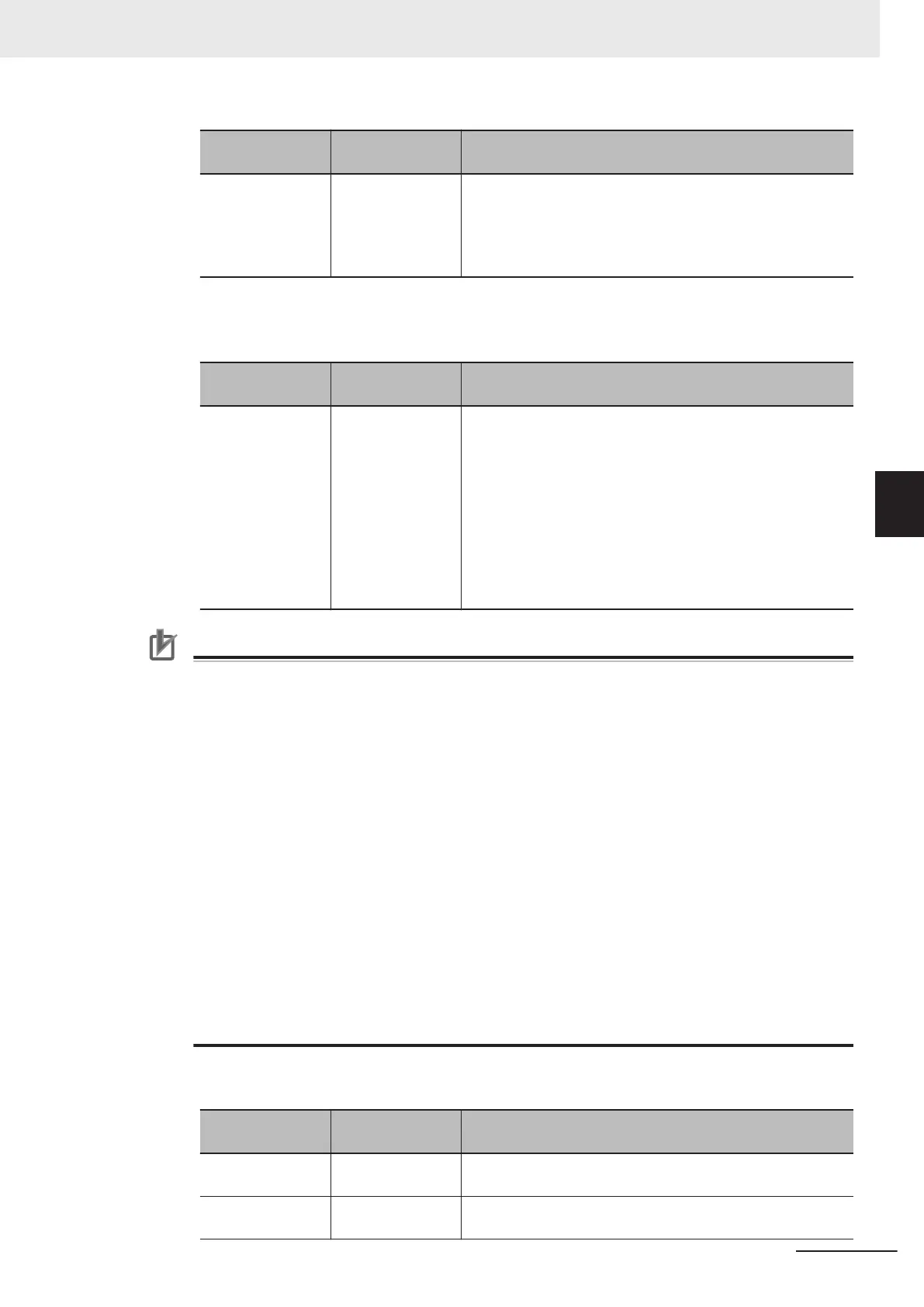
Item
Set value
[Factory default]
Description
Output signal
• [STGOUT]
• SHTOUT
The STGOUT signal line is used for the STGOUT signal.
If you selected STGOUT, you cannot use the SHTOUT out-
put signal.
If you selected SHTOUT, you cannot use the STGOUT out-
put signal.
3 Select the output method of STGOUT signal in the STGOUT setting.
Please uncheck if you select SHTOUT in the Output signal.
Parameter
Set value
[Factory default]
Description
Output without a
Camera connec-
tion
• Checked
• [Unchecked]
• Checked:
STGOUT signals that are not connected with cameras will
output, too.
This setting can be used to change the brightness of the
light quickly.
Use the Electronic flash setting in Camera image input
FH to configure the STGOUT signal.
• Unchecked:
Only STGOUT signal with which a Camera is connected is
output.
Precautions for Correct Use
• The setting of Output even if camera is not connected can be used only with FH series.
• The STGOUT signals that are applicable with the setting Output even if camera is not
connected are as follows.
- FH-1000/2000/3000/5000 series: STGOUT 0 to 7
- FH-L series: STGOUT 0 to 3
• The setting for Multi-line Random-trigger Mode is as follows.
Output signal setting
Configurable only in Output signal setting of Line 0. For other lines settings for Line 0 are-
commonly applied.
Output even if camera is not connected
Selectable for each line.
• If a check is placed for Output even if camera is not connected , set the pulse width for the
Camera Image Input FH processing item of corresponding STGOUT signal (STGOUT0 to
STGOUT7)
For details, refer to Electronic flash setting in the Camera Image Input FH in the Vision
System FH/FHV Series Processing Item Function Reference Manual (Cat. No. Z341).
• STGOUT0 to STGOUT7 is tied to the camera connector number of the sensor controller, not
the camera number. When you use CameraLink Medium Configuration or the Multi-line ran-
dom-trigger mode, confirm the camera connector number that corresponds to the camera
number of Sensor Controller.
4 Set SHTOUT for each line in the Line setting area.
Parameter
Set value
[Factory default]
Description
SHTOUT signal
delay [μs]
0 to 1,000 [0] Sets the delay time from when exposure is completed to
when the SHTOUT signal turns ON in increments of 10 μs.
SHTOUT signal
pulse width [μs]
40 to 10,000
[5,000]
Sets the time to output the SHTOUT signal in increments of
10 μs.
4 Setting the Controller
4 - 43
FH/FHV Series Vision System User’s Manual (Z365-E1)
4-7 Setting the SHTOUT Signal [Output Signal Settings]
4

 Loading...


