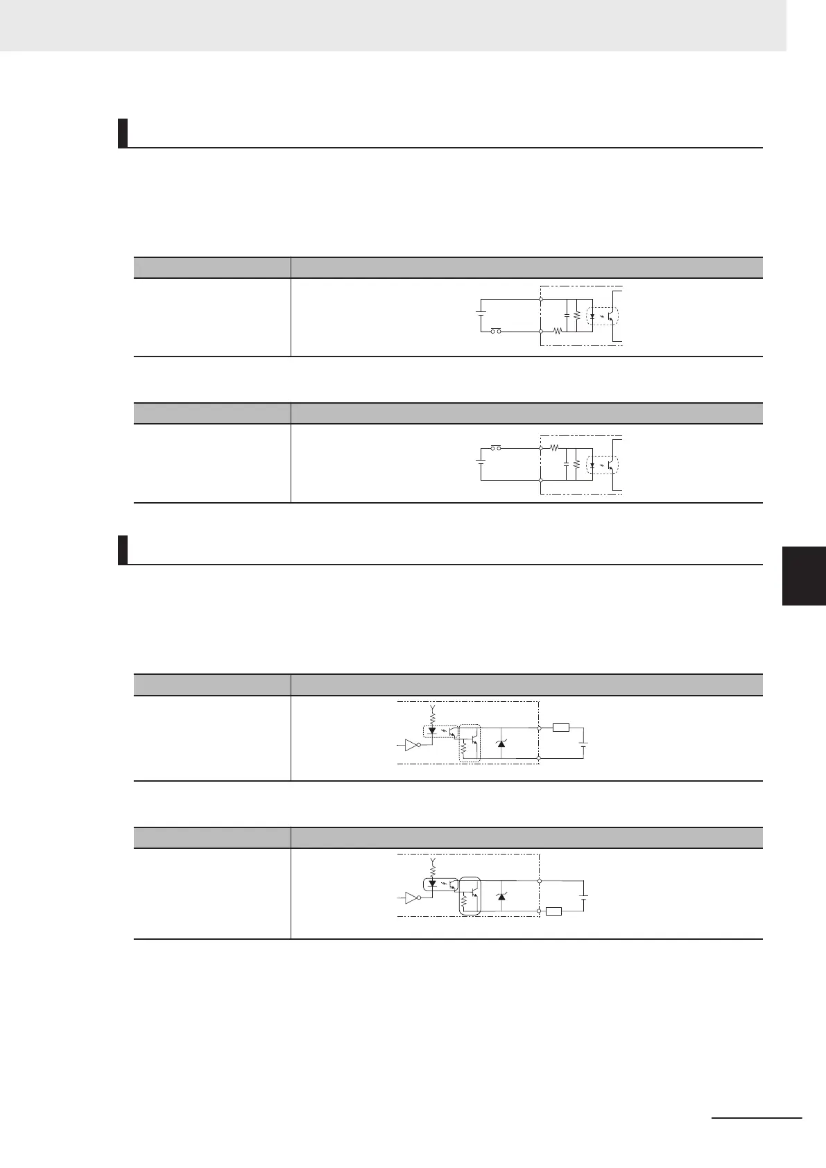
[Input]
Signal
• STEP
Connect to COMIN when using this signal.
a) Internal Specification for NPN connection
Item Specifications
Internal circuit diagram
COM IN
+
Each input terminal
b) Internal Specification for PNP connection
Item Specification
Internal circuit diagram
COM IN
+
Each input terminal
[Output]
Signal
• READY/BUSY/OR/ERROR
Connect to COMOUT when using these signals.
a) Internal Specification for NPN connection
Item Specification
Internal circuit diagram
Each output terminal
Load
COM OUT
+
b) Internal Specification for PNP connection
Item Specification
Internal circuit diagram
COM OUT
+
Each output terminal
Load
6 Power Supply and I/O Interface
6 - 13
FHV Series Smart Camera Setup Manual (Z408-E1)
6-4 I/O Cable Interface (Power Supply, I/O, RS-232C)
6
6-4-5 I/O Interface Input / Output Circuit Diagram

 Loading...


