6-4-5
I/O Interface Input / Output Circuit Diagram
The Parallel Interface is a Common NPN/PNP type. Do the appropriate wiring according to the specifi-
cations of the external device used.
[Input]
Signal
• DI0 to DI2
Connect to COMIN when using these signals.
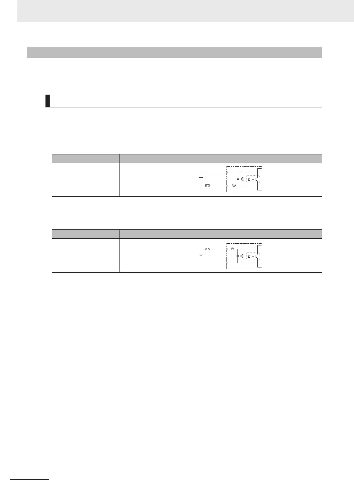
a) Internal Specification for NPN connection
Item Specifications
Internal circuit diagram
COM IN
+
Each input terminal
b) Internal Specification for PNP connection
Item Specification
Internal circuit diagram
COM IN
+
Each input terminal
6 Power Supply and I/O Interface
6 - 12
FHV Series Smart Camera Setup Manual (Z408-E1)

 Loading...


