2.4 Wiring
2-27
INSTALLATION
Note 1. The COM signal on the output connector is connected to the minus terminal of the 24-VDC
power input inside the Cam Positioner.
Note 2. The Vs signal on the output connector is connected to Vs terminal inside the Cam Positioner.
Note 3. For an NPN output, the Vs signal on the output connector is not used.
Note 4. The COM signals on output connectors 1 and 2 are connected inside the Cam Positioner. Also,
the Vs signals are connected inside the Cam Positioner.
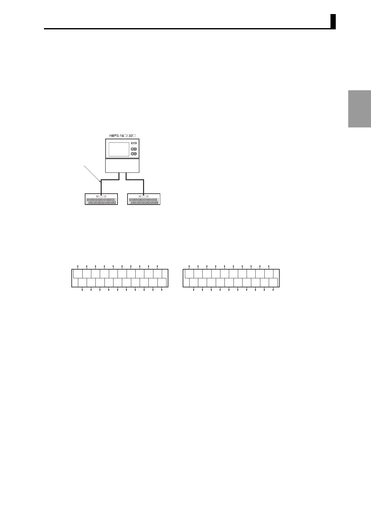
• Using Connector-Terminal Block Conversion Units
XW2D-20G6
Connector-Terminal Block
Conversion Unit (Order Separately)
(CN1)
E5ZE-CBL200
Connector-type
Output Cable
(Order Separately)
Output Cable 2Output Cable 1
(CN2)
1 3 5 7 9 1113151719
2468101214161820
1 3 5 7 9 11 13 15 17 19
2 4 6 8 101214161820
Output Cable 1
Terminal Arrangement of the XW2D-20G6 Connector-Terminal Block Conversion Unit
Output Cable 2
Vs
Vs
COM
COM
Cam 1
Cam 2
Cam 3
Cam 4
Cam 5
Cam 6
Cam 7
Cam 8
Cam 9
Cam 10
Cam 11
Cam 12
Cam 13
Cam 14
Cam 15
Cam 16
Vs
COM
Cam 17
Cam 18
Cam 19
Cam 20
Cam 21
Cam 22
Cam 23
Cam 24
Vs
COM
Cam 25
Cam 26
Cam 27
Cam 28
Cam 29
Cam 30
Cam 31
Cam 32