116 LD Platform OEM User's Guide 11970-000 Rev H1
8.6 Replacing Non-Periodic Parts
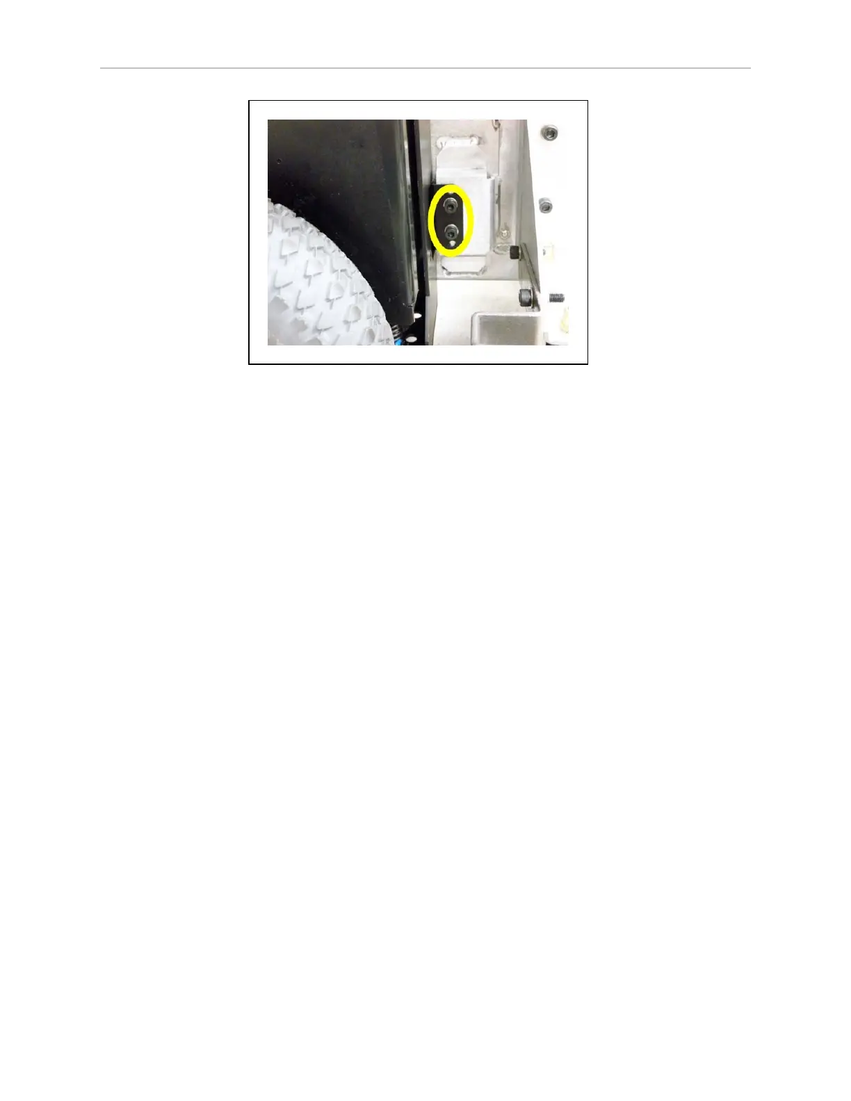
Figure 8-13. Mounting Screws at Bottom-Right of Drive Assembly
8.
Remove the drive assembly from the platform.
The motor cable to the core will still be attached.
9.
Disconnect the motor cable at the drive assembly.
Installation
1.
Lift the new drive wheel up, compressing its springs, enough so that you can insert a 6-
dia. x 10 mm(0.24-dia. x 0.4 inch) pin into the hole on the rear side of the assembly
(there is a hole on each side).
This will keep the springs compressed (the wheel will be in the up position), and make
installation easier.
If you saved a wheel pin when you uncrated the platform, you can use that. An M5 x
10 screw also works well for this. See Spring-Compression Hole on page 115.
NOTE:Make sure that the pin is short enough that you can pull it out after
the assembly is in place.
2.
Connect the motor cable to the new drive assembly.
3.
Install the new drive assembly over the three studs at the top of its bracket.
Use the nuts, screws, and washers you removed from the old drive assembly.
4.
Remove the pin or screw you used to hold the wheel in the up position.
5.
Put the side skin next to the platform, and attach the cable to the light disc PCA.
6.
Reinstall the side skin.
7.
Connect the battery power and data cables, and close the battery compartment door.
8.
Reinstall the rear skin.