54 LD Platform OEM User's Guide 11970-000 Rev H1
5.2 Considerations
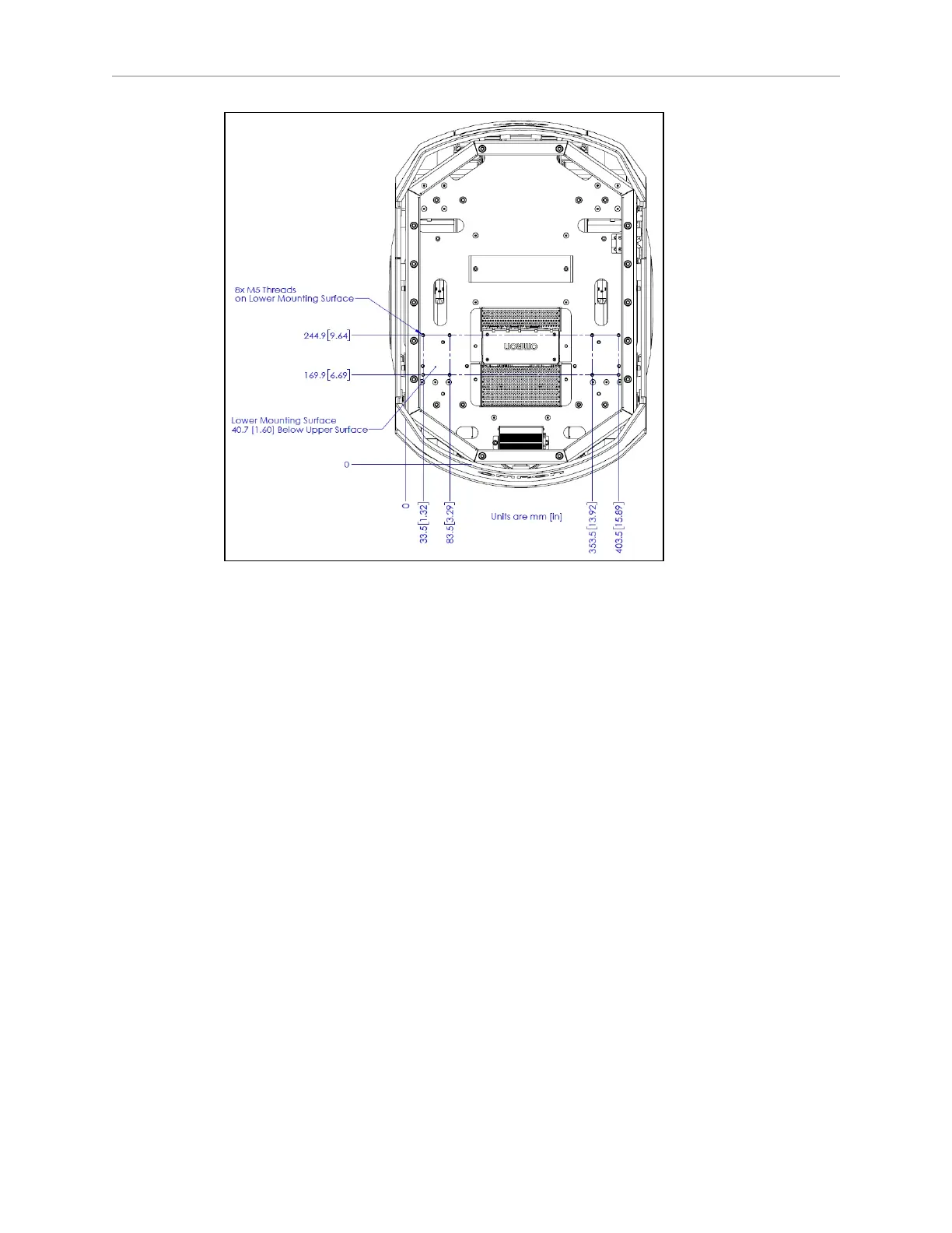
Figure 5-2. Platform Deck Dimensions, with M5-threaded Holes
In the preceding figure, all of the M5 self-clinching nuts (B)have a torque limit of 14 N-m (124
in-lb
f
).
NOTE:The M6 self-clinchingnuts are inserted differently than the M5 self-
clinchingnuts, to increase the usable thread length. This also decreases the torque
that you can apply to them, so the M5s have a much higher torque limit than the
M6s in this application.
Center of Gravity
As much as possible, you should keep the payload structure center of gravity centered on the
platform, and as low (close to the platform top) as possible. This will give you the best sta-
bility, particularly when crossing thresholds or irregularities in the floor.Keep the payload
centered on the platform left-to-right, but biased toward the rear of the platform according to
the following figures.The following figure shows the platform‘s center of gravity, without pay-
load structure.