91
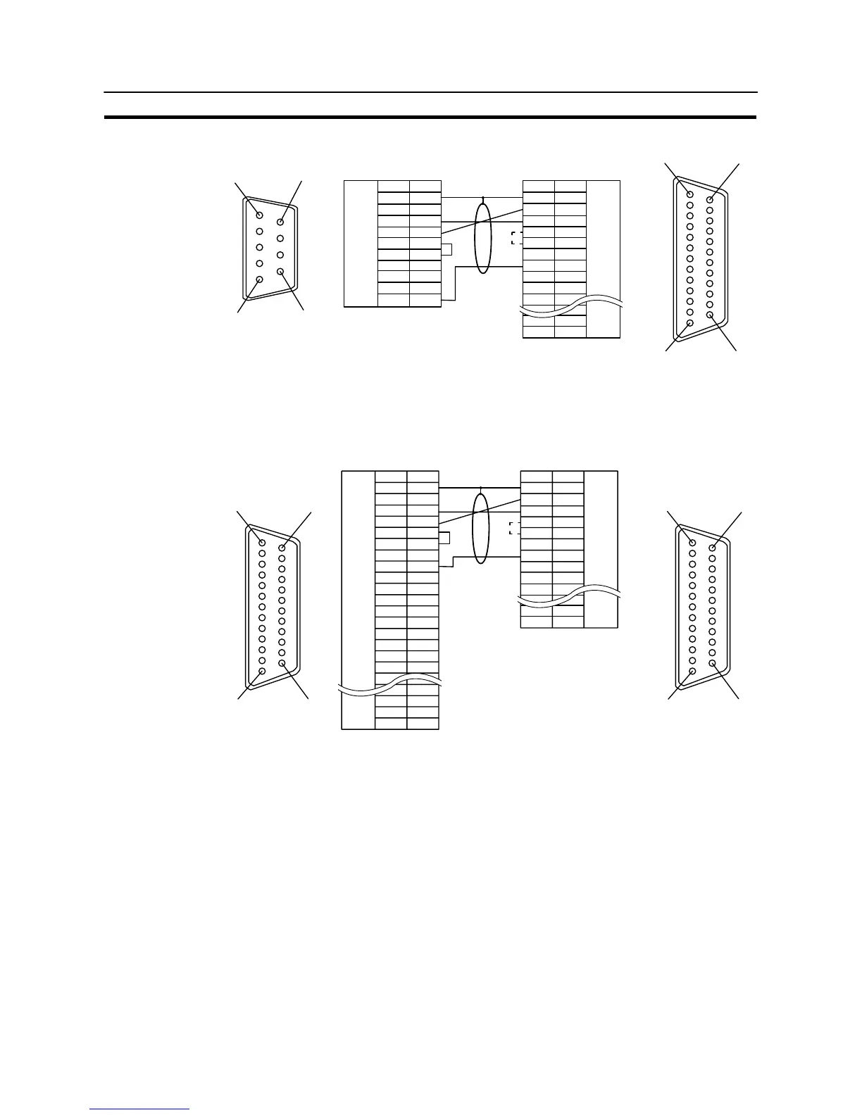
Connecting to the RS-232C Port at the Host
Section 4-1
[Serial port A]
1
6
5
9
*
NT31/NT31C
114
13 25
FG
+5V
CS
RS
RD
SD
5G
1
2
3
4
5
6
7
8
9
1
2
3
4
5
6
7
8
–
–
–
–
FG
5G
CS
RS
RD
SD
ER
–
–
–
–
–
PC (host link unit)
(25-pin type)
(9-pin type)
RS-232C
interface
RS-232C
interface
Abbreviation
Pin
number
Abbreviation
Pin
number
Connector
hood
Shielding wire
* For units that have a CTS setting selector switch, RS and CS do not have to be
shorted if this switch is set to “0V”.
[Serial port B]
–
114
13 25
114
13 25
*
FG
CS
RS
RD
SD
TRM
Abbreviation
–
–
SG
–
–
SDA (–)
RDA (–)
–
RDB (+)
SDB (+)
–
–
–
RSB (+)
RSA (–)
1
2
3
4
5
6
7
8
9
Pin
number
Connector
hood
10
11
12
13
14
15
16
–
23
24
25
–
Abbreviation
Pin
number
1
2
3
4
5
6
7
8
20
–
–
–
–
FG
CS
RS
RD
SD
–
SG
–
–
–
–
ER
NT31/NT31C PC (host link unit)
(25-pin type)
RS-232C/
422A/485
interface
Shielding wire
RS-232C
interface
(25-pin type)
* For units that have a CTS setting selector switch, RS and CS do not have to be
shorted if this switch is set to “0V”.