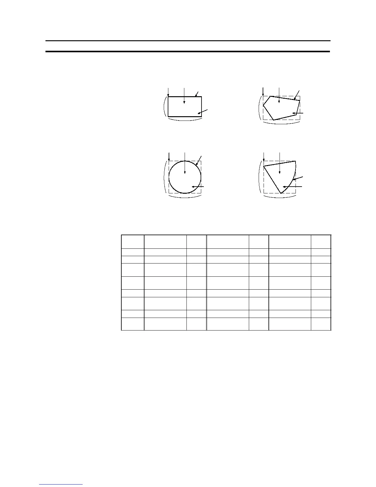
Size
(Y direction)
“ON”/“OFF”
colors
Size (X direction)
LAMP
LAMP
- Allocated bit
Lamp bits can be allocated to the following host (PC) areas.
Symbol C Series PLC
Alloca
tion
CVM1/CV
Series PLC
Alloca
tion
CS1 Series PLC
Alloca
tion
DM Data memory
✓
Data memory
✓
Data memory
✓
CH I/O relay
✓
I/O relay
✓
I/O relay
✓
TIM
Timer present
value
×
Timer present
value
×
Timer present
value
×
CNT
Counter present
value
×
Counter present
value
×
Counter present
value
×
HR Holding relay
✓
# #
Holding relay
×
AR Auxiliary relay
✓
Special
auxiliary relay
×
Special
auxiliary relay
×
LR Link relay
✓
# # # #
EM
Expansion data
memory *1 *2
✓
Expansion data
memory *2
EM current
Bank *2
✓
✓
:OK
×
:NG
:HostlinkNG
*1 C--series EM (Expansion Memory) is available only in the C200HX/HG/HE (-Z).
*2 The EM (Expansion Memory) can be alocated only in the current bank.
Since the special auxiliary relays of the CVM1/CV series PCs are all allocated
to system functions, they cannot be used for purposes other than system use.
The range of each memory area differs according to the PC type. Refer to
APPENDIX L “PC Memory Map”, page 684.
- Display of lamps
Lamps are displayed as follows according to the status of the allocated bit.
0 (OFF): OFF
1 (ON): ON, or flashing