341
Touch Switches
Section 7-7
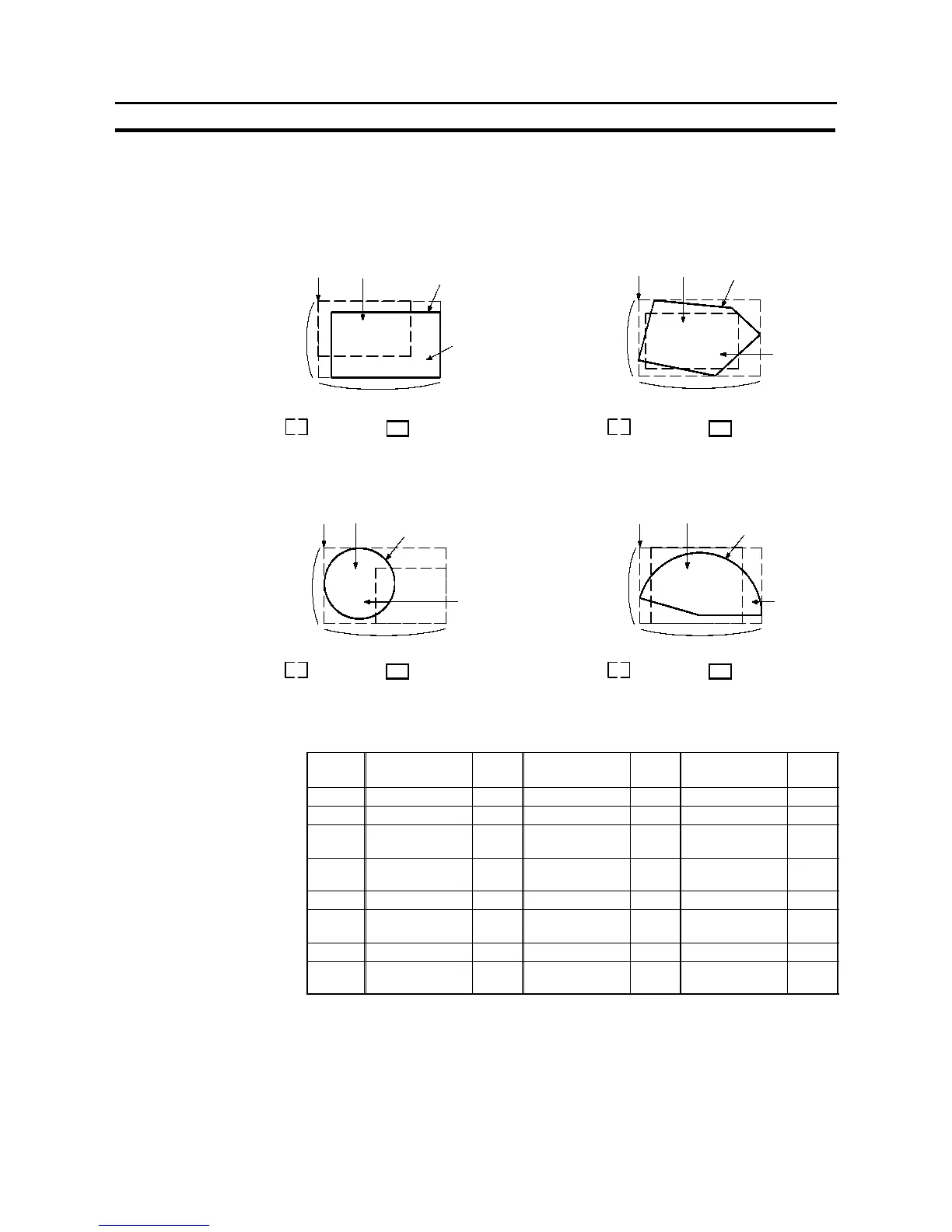
<With free-shape display frame>
When a free-shape display frame is used, the display graphic can be set any-
where, independently of the area that responds as a touch switch (touch switch
area).
Rectangle Polygon
Position “Description”
Frame color
Size
(Y direction)
LABEL
OFF color/
ON color
Size (X direction)
Touch
switch area
Display
graphic
Circle Sector
Position “Description”
Frame color
Size
(Y direction)
LABEL
OFF color/
ON color
Position “Description”
Frame color
Size
(Y direction)
OFF color/
ON color
Position “Description”
Frame color
Size
(Y direction)
OFF color/
ON color
Size (X direction)
Size (X direction) Size (X direction)
Touch
switch area
Display
graphic
LABEL
LABEL
Touch
switch area
Display
graphic
Touch
switch area
Display
graphic
S Allocated bit
Lamp bits can be allocated to the following host (PC) areas.
Symbol C Series PLC
Alloca
tion
CVM1/CV
Series PLC
Alloca
tion
CS1 Series PLC
Alloca
tion
DM Data memory
✓
Data memory
✓
Data memory
✓
CH I/O relay
✓
I/O relay
✓
I/O relay
✓
TIM
Timer present
value
×
Timer present
value
×
Timer present
value
×
CNT
Counter present
value
×
Counter present
value
×
Counter present
value
×
HR Holding relay
✓
# #
Holding relay
×
AR Auxiliary relay
✓
Special
auxiliary relay
×
Special
auxiliary relay
×
LR Link relay
✓
# # # #
EM
Expansion data
memory *1 *2
✓
Expansion data
memory *2
EM current
Bank *2
✓
✓
:OK
×
:NG
:HostlinkNG
*1 C-series EM (Expansion Memory) is available only in the C200HX/HG/HE (-Z).
*2 The EM (Expansion Memory) can be alocated only in the current bank.