608
Examples of Actual Applications of Direct Access
Section 10-1
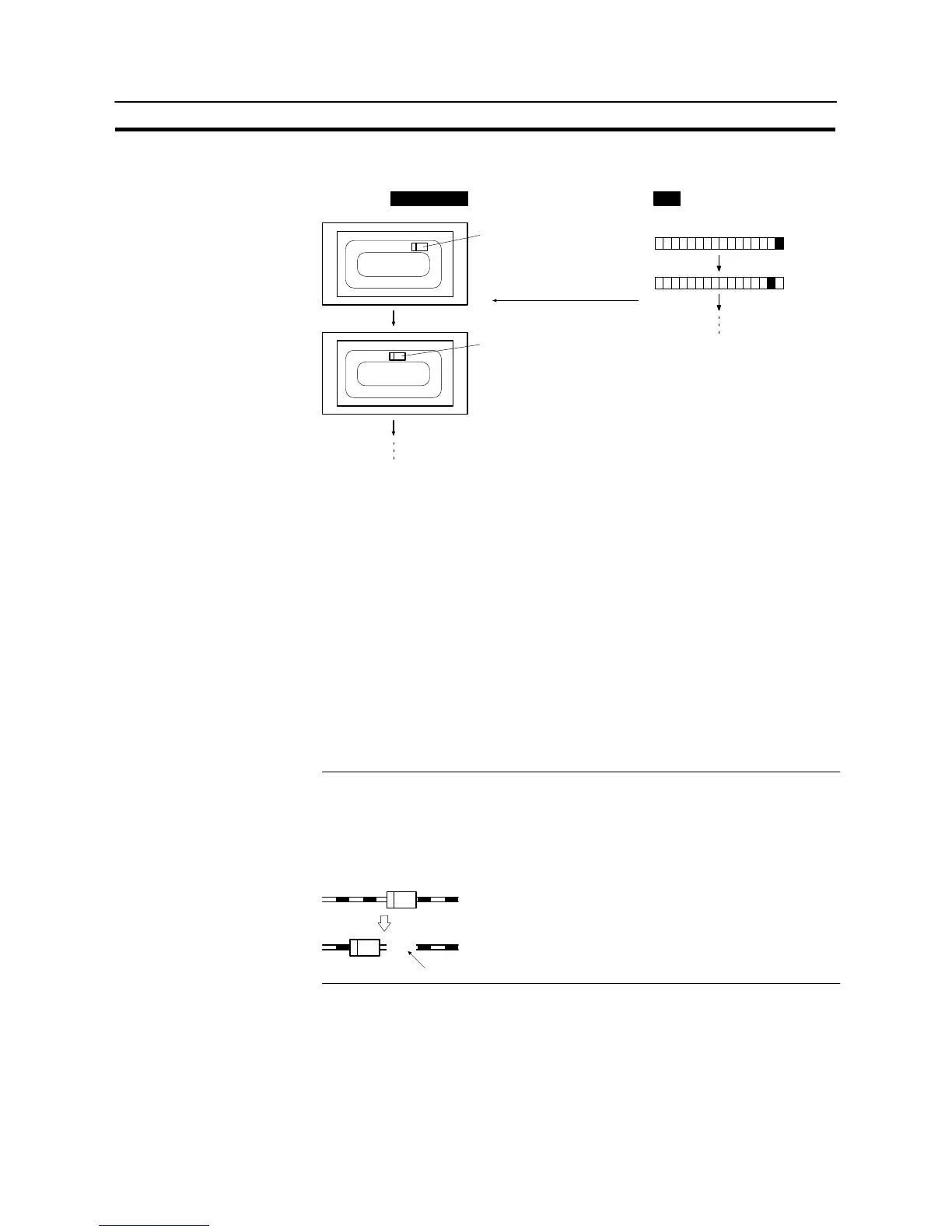
Example: PC bits 0 to 15 come ON according to the position of an automatic guided vehicle,
and the position of the vehicle is shown on the screen.
15 0
Automatic guided vehicle
at bit 0 position
Bits
Automatic guided vehicle
at bit 1 position
PCNT31/NT31C
(1) Create figures depicting the automatic guided vehicle with library data (fixed
display graphics) or image data (composed of dots). If there is a figure with a
different orientation, create it separately.
(2) Register image/library lamp set as shown below for the position correspond-
ing to bit 0 on the screen.
- “OFF State”, “Code”:
Check mark not set
- “ON State”, “Code”:
Check mark set, code for the library data for the automatic guided vehicle
created in (1) (shape corresponding to the position)
- PC Address:
Bit number of bit 0 indicating the automatic guided vehicle’s position
(3) Register image/library lamps set for bits 1 to 15 in the same way as in (2).
Reference: With NT31/NT31C, once an element has been drawn, it is not redrawn unless the
display contents change (this applies even with overlapping screens). Conse-
quently, if a rail is drawn as a fixed display element underneath the automatic
guided vehicle, when the automatic guided vehicle moves, the rail underneath the
position where the automatic guided vehicle was originally placed, cleared togeth-
er as the vehicle moves. Bear this in mind when creating the screen data.
The rail is cleared.