87
Connecting to the RS-232C Port at the Host
Section 4-1
S Connecting to CS1 series serial communication unit
A CS1 series backplane mounted type : CS1W-SCU21-E
[Setting the front switches]
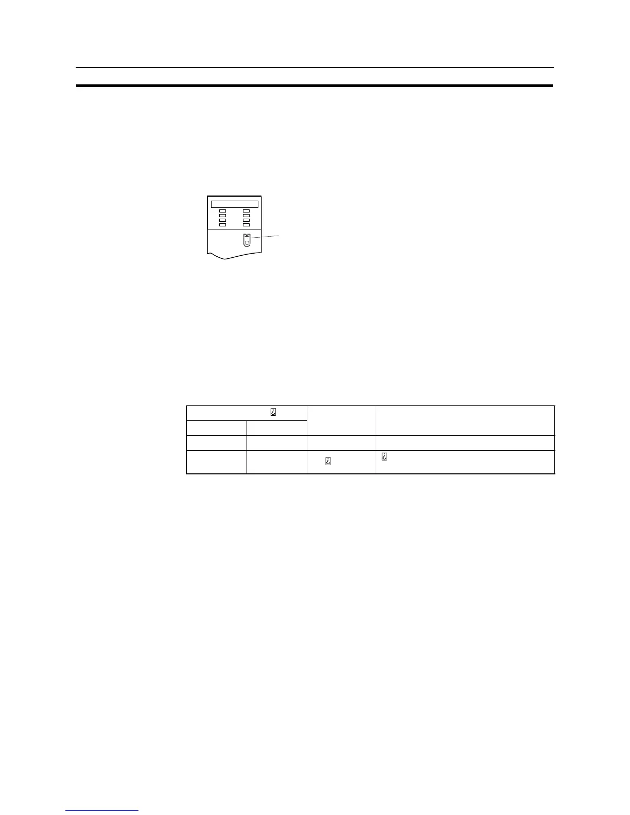
Set the unit number of the serial communication unit by using the rotary switch lo-
cated on the front panel. Set each switch with a flat blade screwdriver so that the
values or symbols in the setting value window agree with the following.
Set the unit number to “0” through “F” so
that it will not overlap with the numbers
used in other units.
SCU21
RUN
ERC
SD1
RD1
RDY
ERH
SD2
RD2
UNIT
No.
F
E
D
C
B
A
9
8
7
6
5
4
3
2
1
0
[Allocation DM area settings for CPU]
Setting is written from the peripheral tool (a programming console or CX-Program-
mer) directly into the allocation DM area (system setting area) of the CPU. After
the setting is written, it becomes effective by turning the power ON, restarting the
unit, restarting the communication port, or execution of the STUP command.
In the following, the channel numbers of the allocation DM area and settings are
shown.
m=DM30000+100*unit number (CH)
Allocation DM area
Port 1 Port 2
Writing Value Settings
m m+10 8200 NT link (1:N) mode
m+6 m+16 000
connected PT (0 – 7)