Appendices
A - 16
NX-series Analog I/O Units User’s Manual for Analog Input Units and Analog Output Units (W522)
Unit name
Analog Input Unit (voltage input type)
Model
NX-AD3604
Number of points
4 points
External connection
terminals
Screwless clamping terminal block (12 ter-
minals)
I/O refreshing method
Free-Run refreshing
Indicators
TS indicator
Input method
Differential input
Input range
-10 to +10 V
Input conversion range
-5 to 105% (full scale)
Absolute maximum
rating
±15 V
Input impedance
1 MΩ min.
Resolution
1/8000 (full scale)
Overall
accuracy
25
°
C
±0.2% (full scale)
0
to
55
°
C
±0.4% (full scale)
Conversion time
250 μs/point
Dimensions
12 (W) x 100 (H) x 71 (D)
Isolation method
Between the input and the NX bus: Power
= Transformer, Signal = Digital isolator (no
isolation between inputs)
Insulation resistance
20 MΩ min. between isolated circuits (at
100 VDC)
Dielectric strength
510 VAC between isolated circuits for 1
minute at a leakage current of 5 mA max.
I/O power supply
method
No supply
Current capacity of I/O
power supply terminal
Without I/O power supply terminals
NX Unit power con-
sumption
• Connected to a CPU Unit
1.35 W max.
• Connected to a Communications Cou-
pler Unit
1.10 W max.
Current consumption
from I/O power supply
No consumption
Weight
70 g max.
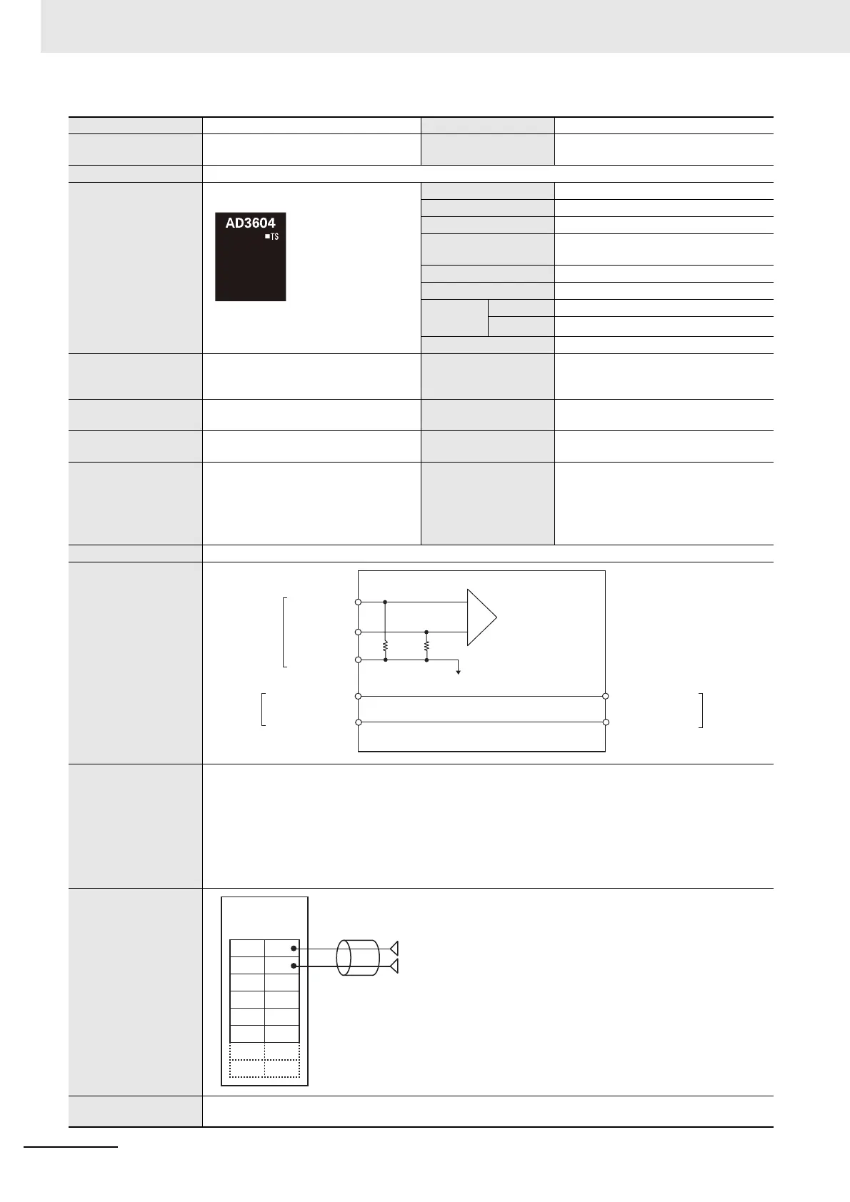
Circuit layout
Installation orienta-
tion and restrictions
Installation orientation:
• Connected to a CPU Unit
Possible in upright installation.
• Connected to a Communications Coupler Unit
Possible in 6 orientations.
Restrictions: No restrictions
Terminal connection
diagram
Input disconnection
detection
Not supported.
AMP
AG
AG
Input1+ to 4+
Terminal block
Input1
−
to 4
−
510 KΩ510 KΩ
AG: Analog circuit
internal GND
NX bus
connector
(left)
I/O power supply +
I/O power supply −
I/O power supply +
I/O power supply −
NX bus
connector
(right)
AG
A1 B1
A8 B8
AG
AG
AG
AG terminal is connected to 0 V of analog circuit inside the Unit.
It is not necessary to wire AG terminal normally.
Input +
Input −
Input1+
Voltage Input Unit
NX-AD3604
Input1−
Input2+
Input2−
Input3+
Input3−
Input4+
Input4−
 Loading...


