4 Installation and Wiring
4 - 26
NX-series Analog I/O Units User’s Manual for Analog Input Units and Analog Output Units (W522)
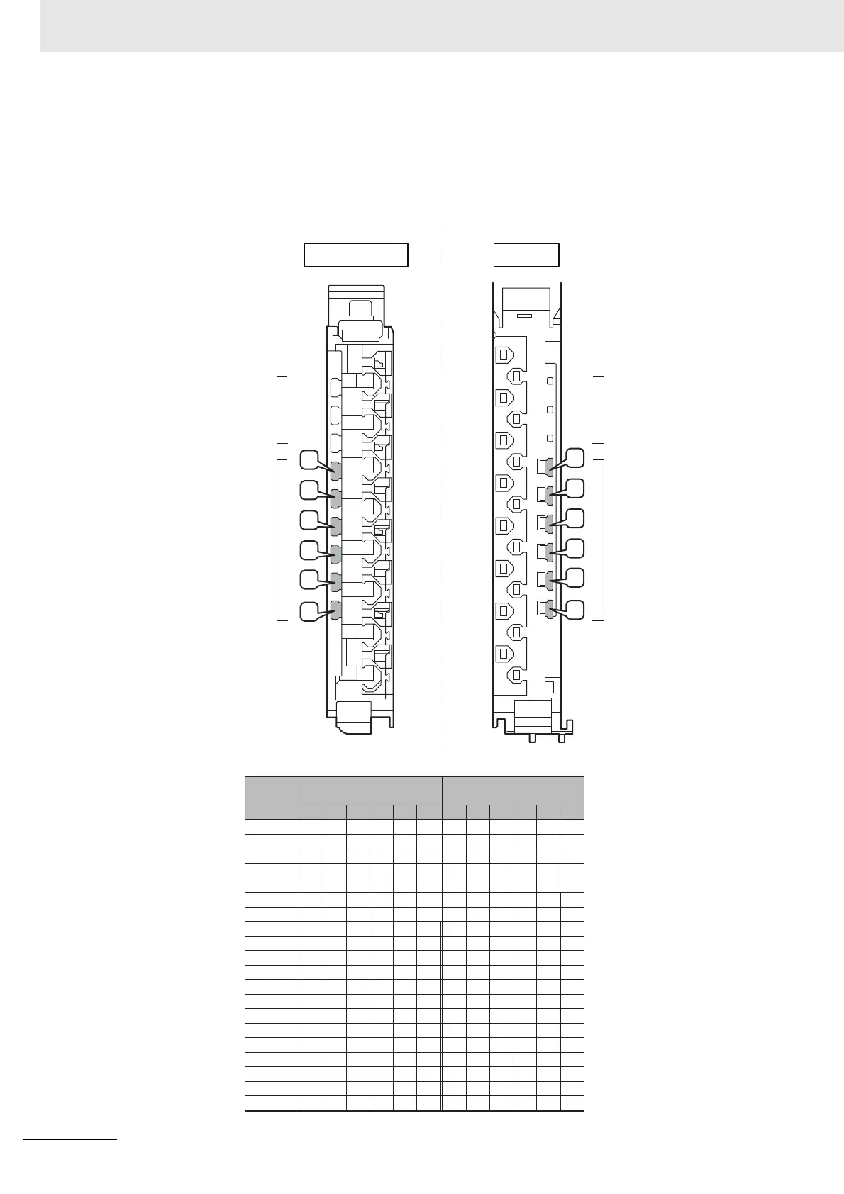
z Insertion Locations and Patterns of Coding Pins
Insert three Coding Pins of each on the terminal block and on the Unit at the positions designated by
the numbers 1 through 6 in the figure below.
As shown in the following table, there are 20 unique pin patterns that can be used.
Pin locations for
terminal block
○: Pin inserted
Terminal block Unit
123 45 6
○No.1 ○ ○
○No.2 ○ ○
○No.3 ○ ○
○No.4 ○ ○
○No.5 ○ ○
○No.6 ○ ○
○No.7 ○ ○
○No.8 ○ ○
○No.9 ○ ○
○No.10 ○ ○
No.11 ○ ○ ○
No.12 ○ ○ ○
No.13 ○ ○ ○
No.14 ○ ○ ○
No.15 ○ ○ ○
No.16 ○ ○ ○
No.17 ○ ○ ○
No.18 ○ ○ ○
No.19 ○ ○ ○
No.20 ○ ○ ○
123456
○○○
○○○
○○○
○○○
○○○
○○○
○○○
○○○
○○○
○○○
○○○
○○○
○○○
○○○
○○○
○○○
○○○
○○○
○○○
○○○
1
2
3
4
5
6
1
2
3
4
5
6
Holes used by
OMRON
Holes for incorrect
attachment prevention
(pin locations)
Pin locations for Unit
Pattern
Holes used by
OMRON
Holes for incorrect
attachment prevention
(pin locations)
 Loading...


