Appendices
A - 52
NX-series Digital I/O Unit User’s Manual (W521)
Unit name
Transistor Output Unit
Model
NX-OD3268
Number of points
4 points
External connection
terminals
Screwless clamping terminal block (16 ter-
minals)
I/O refreshing method
Switching Synchronous I/O refreshing and Free-Run refreshing
Indicators
TS indicator, output indicator
Internal I/O common
PNP
Rated voltage
24 VDC
Operating load voltage
range
15 to 28.8 VDC
Maximum value of load
current
2 A/point, 8 A/Unit
Maximum inrush cur-
rent
4.0 A/point, 10 ms max.
Leakage current
0.1 mA max.
Residual voltage
1.5 V max.
ON/OFF response time
0.5 ms max./1.0 ms max.
Dimensions
12 (W) x 100 (H) x 71 (D)
Isolation method
Photocoupler isolation
Insulation resistance
20 MΩ min. between isolated circuits (at
100 VDC)
Dielectric strength
510 VAC between isolated circuits for 1
minute at a leakage current of 5 mA max.
I/O power supply
method
Supply from external source
Current capacity of I/O
power supply terminal
IOV
: 2
A/terminal max., IOG
: 2
A/terminal
max., COM (+V): 4 A/terminal max., 0V: 4
A/terminal max.
NX Unit power con-
sumption
• Connected to a CPU Unit
0.85 W max.
• Connected to a Communications Cou-
pler Unit
0.50 W max.
Current consumption
from I/O power supply
20 mA max.
Weight
70 g max.
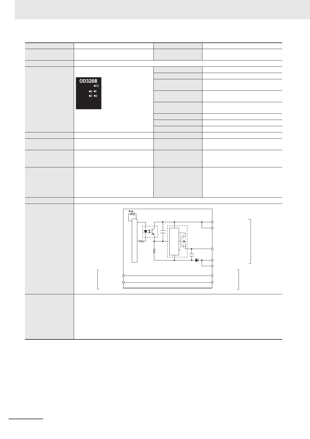
Circuit layout
Installation orienta-
tion and restrictions
Installation orientation:
• Connected to a CPU Unit
Possible in upright installation.
• Connected to a Communications Coupler Unit
Possible in 6 orientations.
Restrictions: No restrictions
OUT 0 to OUT 3
IOG 0 to IOG 3
IOV 0 to IOV 3
COM (+V)
0V
I/O power
supply +
NX bus
connector
(left)
I/O power
supply −
NX bus
connector
(right)
I/O power
supply +
I/O power
supply −
Terminal block
Internal circuits
Short-circuit
protection