EasyManuals Logo

Omron NX1P2 series User Manual

Omron NX1P2 series
340 pages
To Next Page IconTo Next Page
To Previous Page IconTo Previous Page
Page #197 background imageLoading...
Page #197 background image
5 - 65
5 Installation and Wiring
NX-series NX1P2 CPU Unit Hardware User’s Manual (W578)
5-4 Wiring
5
5-4-10 Wiring the NX1W-CIF01 Serial Communications Option Board
This section explains how a communications cable which is connected to the NX1W-CIF01 is con-
nected to an external device through wiring to a D-sub connector.
Use the following steps to wire connectors.
See the following diagrams for the length of the cable portion to be cut in each step.
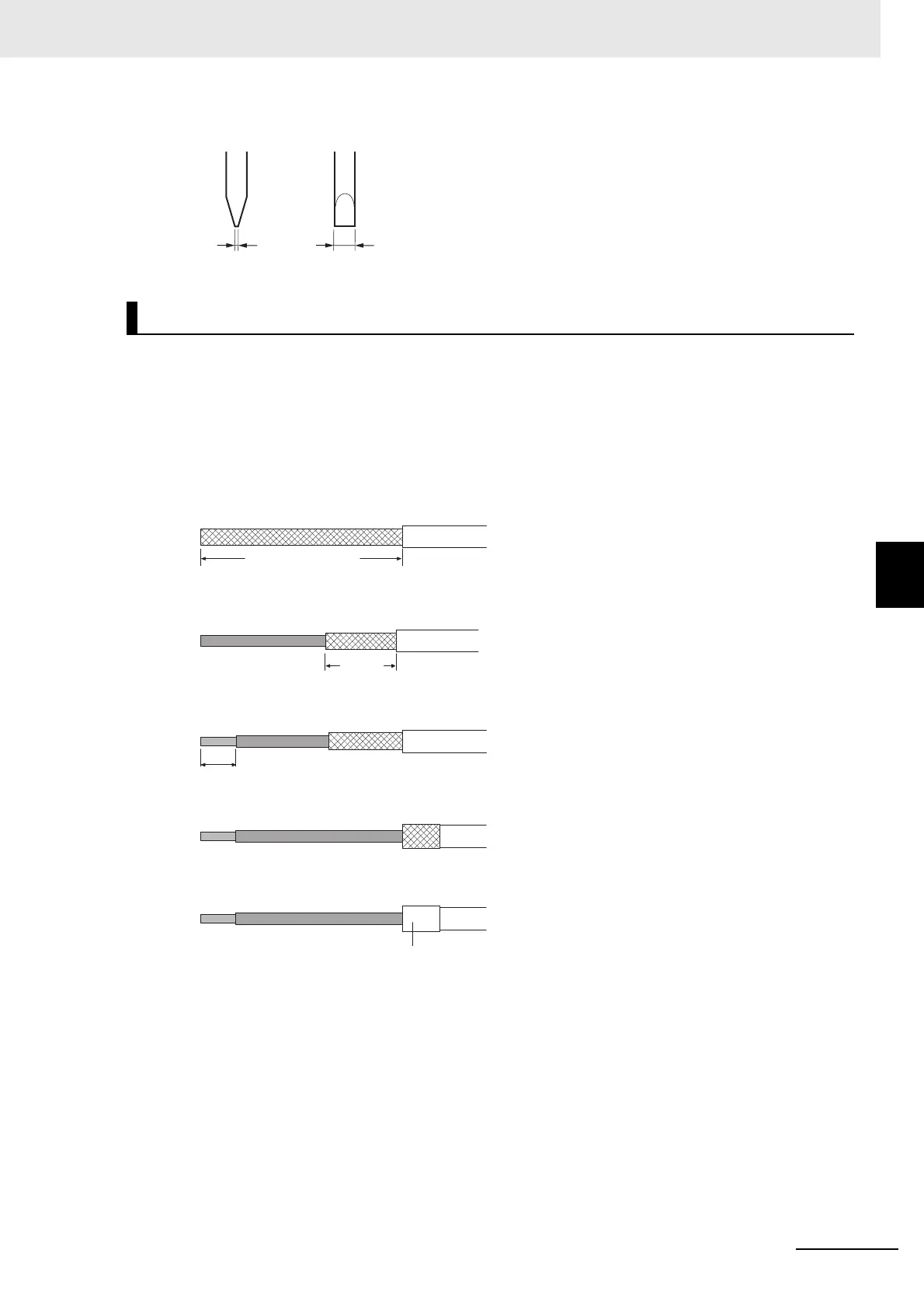
1 Cut the cable to the required length.
2 Remove the specified length of the sheath.
Be careful not to scratch the braided shield.
3 Trim off the braided shield using scissors.
4 Remove the insulation from each conductor using a stripper.
5 Fold back the braided shield.
6 Wrap an aluminum foil tape around the folded shield.
Wiring to the D-sub Connector
Side view
Front
1 mm max.
2 mm max.
40 mm (RS-232C)
10 mm
5 mm
Aluminum foil tape

Table of Contents

Other manuals for Omron NX1P2 series

Questions and Answers:

Question and Answer IconNeed help?

Do you have a question about the Omron NX1P2 series and is the answer not in the manual?

Omron NX1P2 series Specifications

General IconGeneral
ModelNX1P2 Series
ManufacturerOmron
TypeController
CPU Units1
Program Capacity5 MB
Data Memory Capacity128 KB
Ethernet Ports1
Serial Ports1
Built-in EtherNet/IP PortYes
Built-in EtherCAT PortYes
Built-in USB PortYes
SD Memory Card SlotYes
USB Port1
Power Supply Voltage24 VDC
Programming LanguageLadder, Structured Text, Function Block Diagram
Communication ProtocolsEtherNet/IP, EtherCAT, Serial (RS-232C)

Related product manuals