8-13
8-2 Gain Parameters
OMNUC G5-SERIES AC SERVOMOTOR AND SERVO DRIVE USER'S MANUAL
8
Parameter Details
Explanation of Settings
(√: Enabled, −: Disabled)
Select the conditions for switching between gain 1 and gain 2 when the Gain Switching Input
Operating Mode Selection (Pn114) is set to 1.
The gain is always gain 1 regardless of the gain input if the Gain Switch input is not assigned to
any input if this setting is 2.
*1. The Gain Switching Delay Time in Position Control (Pn116) becomes effective when the gain is
switched from 2 to 1.
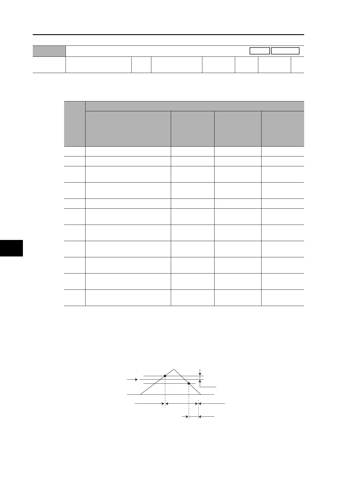
*2. The Gain Switching Hysteresis in Position Control (Pn118) is defined in the drawing below.
*3. The variation means the change amount in a millisecond (ms).
E.g. The set value is 200 when the condition is a 10% change in torque in 1 millisecond.
*4. This is the encoder resolution.
Pn115
Switching Mode in Position Control
Setting
range
0 to 10 Unit −
Default
setting
0
Power OFF
and ON
−
Set
value
Explanation
Gain switching conditions
Gain Switching
Delay Time in
Position
Control
(Pn116)
*1
Gain Switching
Level in Position
Control (Pn117)
Gain Switching
1 Hysteresis in
Position
Control
(Pn118)
*2
0 Always Gain 1 (Pn100 to Pn104) −− −
1 Always Gain 2 (Pn105 to Pn109) −− −
2
Switching using gain switching
input (GSEL) for CN1 pin 27
−− −
3
Torque command variation (Refer
to Figure A)
√
√
*3
(× 0.05%)
√
*3
(× 0.05%)
4 Always Gain 1 (Pn100 to Pn104) −− −
5
Command speed (Refer to Figure
B)
√√ (r/min) √ (r/min)
6
Amount of position error (Refer to
Figure C)
√√
*4
(pulse) √
*4
(pulse)
7
Command pulses received (Refer
to Figure D)
√− −
8
Positioning completion signal (INP)
OFF (Refer to Figure E)
√− −
9
Actual motor speed (Refer to
Figure B)
√√ (r/min) √ (r/min)
10
Combination of command pulse
input and speed (Refer to Figure F)
√√
*5
(r/min) √
*5
(r/min)
Pn117
0
Pn118
Pn116
Gain 1
Gain 2
Gain 1
 Loading...


