No.18S111-03
16/70
STC-MBS500POE / STC-MCS500POE
Product Specifications and User’s Guide
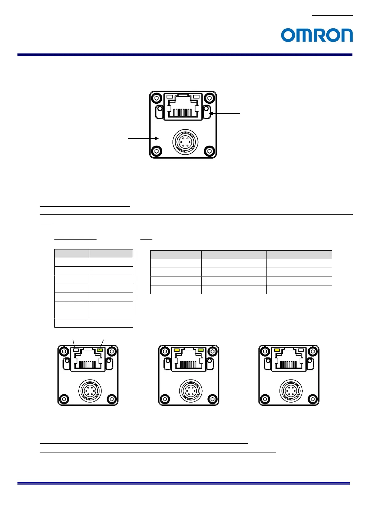
6 Connector Specifications
6.1 RJ45 Connector
This product is PoE compliant.
Please supply power (+10.8 to +26.4 Vdc) through the power-I/O connector when using non-PoE-compliant
NIC.
Pin Assignment LED
Pin No. Signal Name
1 TA+
2 TA-
3 TB+
4 TC+
5 TC-
6 TB-
7 TD+
8 TD-
Please use a 1GB supported NIC, Network Switcher and Ethernet cable.
Check the setting of NIC and Network Switcher being used is “1GB transferring”.
Green LED Yellow LED Status
Green Light ON Yellow Light OFF Power ON (1GB NIC)
Green Light OFF Yellow Light OFF Power ON (100MB NIC)
Green Light ON Yellow Light Blinking 1 GB Transferring
Green Light OFF Yellow Light Blinking 100 MB Transferring
Camera is powered-on
Green light: ON
Yellow light: Blinking
1 GB Transferring
Green light: OFF
Yellow light: Blinking
100 MB Transferring
Power-I/O Connector
RJ45 Connector
Yellow LED Green LED
 Loading...


