No.18S111-03
30/70
STC-MBS500POE / STC-MCS500POE
Product Specifications and User’s Guide
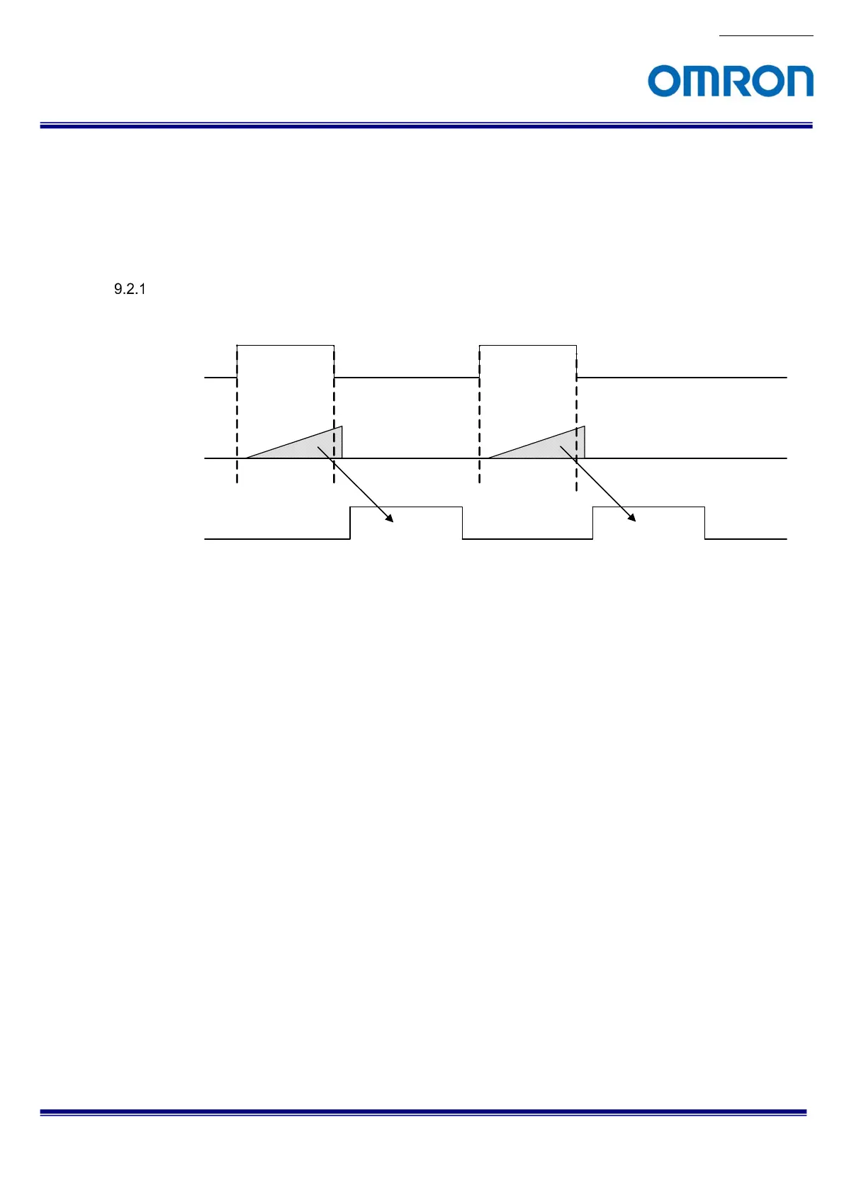
9.2 Pulse width trigger mode
In this trigger mode with positive polarity, the expose starts at rising edge of trigger signal and stops at falling edge
of trigger signal. The expose period is high states of trigger signal.
In this trigger mode with negative polarity, the expose starts at falling edge of trigger signal and stops at rising
edge of trigger signal. The expose period is low states of trigger signal.
Timing
Expose
Image out
Trigger signal
(Positive polarity)
Note: The exposure time is active pulse duration of trigger signal.
Please refers “Exposure Timing” for more details.
 Loading...


